Download
1 / 10
100 likes | 229 Views
Test of the high voltage strength of Pelletron’s gas insulation (18-Dec-2008). Recycler Meeting January 21, 2009 A. Shemyakin. Introduction. By now, we are almost certain that SF6 gas in the Pelletron tank is heavily contaminated by air (up to 40%).

E N D
Test of the high voltage strength of Pelletron’s gas insulation (18-Dec-2008) Recycler Meeting January 21, 2009 A. Shemyakin
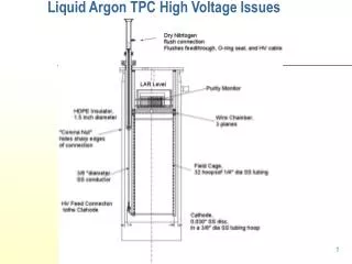
Introduction • By now, we are almost certain that SF6 gas in the Pelletron tank is heavily contaminated by air (up to 40%). • Cost of replacement by a pure SF6 is ~100 k$ • The Pelletron performance can be affected by the contamination in several ways • Increased frequency of equipment failures due to a high oxygen content • A serious concern; however, there were no failures in the last 2 months • Replacing today’s gas by a SF6 + N2 mixture would be a solution • Possible changes in cooling efficiency of elements inside the tank • Data logger data do not show any measurable changes • Changes in HV electric insulation properties of the gas • Subject of the test • Question for the test to answer: • How close is the operational voltage to the HV limit in the gas?
Two types of HV limitation in the Pelletron • Emission and finally a discharge in vacuum • The main limit in operation • Much worse with the beam in the tube • Back in 2004, it was the reason to increase the total length of acceleration tubes • Always accompanied by a burst in the vacuum pressure • Should not significantly depend on properties of the outside gas • Discharge on the gas side • Before the test, there was only one instance of gas –side discharge in this Pelletron • The first day of HV operation in WB, in air • Strongly depends on the gas type and pressure • In operation, the HV strength in the gas should always exceed the one in vacuum. Section of acceleration tube.
SF6 as an insulation gas • Two types of SF6 applications • Arc quenching in breakers • needs pure SF6 • HV insulation • While pressurized, most of effect is reached by adding a small portion of SF6 to N2 230kV/cm 6% Conversion: 1 atm = 14.7 psi 73.5 psig = 6 atm abs 60 Hz AC breakdown voltage for SF6/N2 mixture. Just straight line DC breakdown voltage. From IEE Trans.on Dielectric and Electric Insulation, V2 N5 (1995), p.977 Range where the test was done
Motivation for the HV test • Because dependence on N2 contamination is weak, one may hope that operation with 60% of SF6 in the mixture is OK • Still, it’s better to make sure by a direct measurement • Usually, such measurements are done by conditioning and observing full discharges until the breakdown level is reproducible • We prefer to have the gas strength is ~twice above the HV strength on the vacuum side • To protect the tubes during discharges in vacuum • Also, we are afraid of breaking the equipment in the Pelletron in the time of discharges • The idea of the HV test • Look at the lost current as a precursor of a full discharge • Make measurements at several values of the gas pressure to interpolate toward the nominal one R1 R2 R2/R1= e; R1 = 1m; Eterm= Uterm/R1; For Uterm= 5 MV Eterm= 50 kV/cm
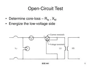
Lost current Lost current from terminal • The current lost from the terminal can be calculated from the balance of currents in the Pelletron column • R:LOSTI = Chain current -(Current through all resistive dividers + Needle current) • Works only for a steady state • If the terminal voltage changes, the R:LOSTI reading needs to be corrected • If changes are not fast (several sec), • Rterm*Cterm ~15 sec • R1*C1~ 1 sec Terminal-to-tank capacitance Needle current R1 C1 Chain current Corona current through the last gaps Resistive divider current (3)
Typical measurement HV test at 50.2 psig. Large peaks of R:LOSTI correspond to fast increasing of HV. Also, it has ~ -2 microA offset. HV (R:GVMVLT), 0.5MV/div Chain current (R:CHN1I), 20microA/div Lost current (R:LOSTI), 4microA/div Pressure (R:IGA06), 1.E-09/div 0 Here the lost current never comes to its minimum steady state level. 30 min
Corrected Lost current • Example of data with Lost current corrected with the HV time derivative • The first voltage increase at 60.2 psig • Later HV was increased up to 4.9 MV, so the dust redistribution is probably significant • For this measurement, the point of the Lost current jump is taken as the “limitation”
Results • “Limitation” points were determined typically by “noticeable” changes in the lost current • Maximum voltage • At 70 and 60 psig, HV was eventually limited by vacuum activity • At 28 psig, HV was increased up to a full discharge • For other pressure values, the rise of the lost current was too scary Vacuum limit HV limitations at various gas pressure in the Pelletron tank. Blue line indicates maximum observed voltage at the given pressure. Brown dashed line is a rough extrapolation from the point with a full discharge based on the data for pure SF6 from Slide 4. It promises a safety factor of 1.9 at nominal pressure.
Summary • There is a good safety factor in the HV strength of gas insulation in the Pelletron • Most likely, the strength is close to its design value, and the gas contamination does not have a dramatic impact on HV performance of the Pelletron • From the point of view of HV strength, replacing the gas by a pure SF6 is not needed • Judging by this measurement and by the publish data, adding small amount SF6 or N2 into the tank in a case of a leak should have a similar effect • The procedure used in the test for determining the limiting voltage with the lost is not reliable enough to be used in a quantitative scaling • After each gas manipulation, the lost current first appeared at a significantly lower voltage than it eventually did after several voltage increases. Therefore, a necessity of conditioning the gas side after accessing the tank could be related primarily to the gas transfers and to the access itself.