Download
1 / 32
320 likes | 333 Views
Development and Design of DC machines. Contents: Construction, Voltage formula and Output Equation, Armature winding and insulation and The magnetic circuit Armature reaction and field winding design, Commutation and commutating pole design

E N D
Development and Design of DC machines Contents: Construction, Voltage formula and Output Equation, Armature winding and insulation and The magnetic circuit Armature reaction and field winding design, Commutation and commutating pole design Losses, efficiency and temperature rise and Characteristic dc machine
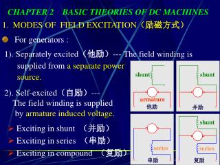
CONSTRUCTION Direct current generators and motors may be divided into three general classes: • The non-commutating-pole machine, use only for generators and motors for low voltages and small capacities. • The commutating pole machine is built with small poles between the main poles and is magnetized by a winding in series with the armature. • The compensated machine, as a modified commutating-pole machine.
The type of construction generally used for direct current generators and motor Figure 1 Assembly drawing of direct current generator 300 kW, 900 r.p.m., 250 Volt.
The spider of a direct current generator or motor is the frame upon which the armature laminations are assembled. By designing the spider with large axial ventilating ducts, good ventilation of the inside of the armature is obtained and the weight of the armature is kept small. The spider for large machine is either a steel casting or is fabricated from rolled steel. Figure 2 shows a cast steel spider of a large-diameter, slow speed machine. Figure 3 is used, that is, the spider is part of the armature lamination.
The armature of direct current generators and motors is built up of electric sheet steel laminations varying in thickness from 0.0141 to 0.025 in. The laminations are punched to correct size by means of dies, carefully annealed and insulated.The usual method of insulating the armature punching is that of applying a thin coat of core plate varnish to each side of the punching. Paper is sometimes used to insulate the armature laminations from one another. The paper is applied to the sheet steel before it is punched out. The insulated armature punching is assembled on the spider between two end plates. The tooth support generally consists of a piece of rolled steel, spot welded to the end lamination. The armature coils are placed into the slots with the required amount of insulation between armature iron and coils, and the slots are sealed with wedges. The type of wedge generally used is of horn fiber impregnated with paraffin. Figure 4 One segment for large diameter armature with welded duct spacer. Figure 5.a and b.The position and thickness of the wedge.
Bands of phosphor bronze or steel wire are used to hold the armature coil end connections in position. The slots are not always sealed by wedges; they are sometimes left open and the coils held in place by phosphor bronze or steel band wires as Figure 6 shows. Figure 6 Complete armature for 7 1/2 h.p., 1750 r.p.m., 230 Volt, 4 pole, shunt wound motor
The commutator is built up of hard drawn, cooper segments, insulated from one another by mica. The thickness of the mica insulation varies from 0.02 to 0.06 in. and depends upon the diameter of the commutator and the voltage between adjacent segments. Figure 7 Armature and commutator assembly, 50 h.p., 850 r.p.m., shunt wound motor.
Field poles • The main poles of most modern machines ate built up of sheet steel laminations, usually from 0.025 to 0.05 in. thick. The laminations are riveted together with no insulation between them. Figure 8 shows the usual shape of the laminations, with pole body and pole shoe punched in one piece. The objection to the cast steel pole construction lies in the fact that it is difficult to obtain castings of uniform material and free from detects. With open armature slots, the type generally used for direct current motors and generators, cast steel pole shoes can not be use, because of the excessive eddy current losses in the pole face due to the air gap flux pulsations produced by the armature slots. Figure 8 Detail drawing of pole punching, 50 kW, 1200 r.p.m., generator
Field Yoke • The yoke is frame to which the field poles are bolted (see Figure 9). The section of the yoke must have the required area for the flux and must also have the required mechanical strength to support the machine. Figure 9 Field yoke with partially assembled field poles, 7 1/2 h.p., 4 pole, motor
The bearings of most modern direct current machines are of the ring oiling type. The bronze bearing is generally preferred for small machines; for large motors and for the larger generators Babbitt bearings are used. Figure 10 cross section of sleeve bearing and bearing housing
Brush Holder and Brush Yoke • Figure 11 shown the brush holders are mounted on studs or arms which are generally bras rods, from ½ to 1 in. in diameter. The brush studs are pressed into openings properly spaced in the bearing bracket. Figure 12 shown one type of brush yoke with brush arms, brush holders, and brushes. Figure 11 Brush holders with brush Figure 12 Brush yoke
Base • All belted type motors and generators are mounted on a belt- tightener base or on rails. The base or rails are bolted down, and the machine can be moved on the base by means of a ratchet device. Figure 13 Belt tightener base
VOLTAGE FORMULA AND OUTPUT EQUATION Volt Voltage Formula : where E is the voltage induced in the armature winding between adjacent brushes. lines The flux per pole, The hypothetical total flux, where fd =the field form distribution factor, which itis the ratio of the area under the true to the area of the hypothetical rectangular field form. lines =
The armature output of a direct current generator, expressed in kilowatts, is as follows: Kwa = E IaX 10-3 [kW] • Output Equation Substituting with E, so Kwa = The total flux is equal to the product of gap area times the maximum air gap density, = πDlBglines. If Q equals the ampere conductors per inch of armature periphery, Q = Kwa= So, The value of Bg, the maximum air gap density, limited by the permissible value of Bt2, the maximum tooth density. Bt2 = lines per sq. in.
Air gap densities that may be used for preliminary design may be taken from the curve, Figure 14. Figure 14. Air gap densities for direct current generators and motors
Average values of Q for commutating pole machines are given in Figure 15. Figure 15 Ampere conductors per inch of armature circumference for commutating pole, direct current generators and motors
Average values of the output constant for commutating pole machines for 50o C. rating may be taken from the curves, Figure 16. Figure 16. Output constants for commutating pole, direct current generators and motors
The induced voltage in a motor armature • E = ET – IaRc volts • Multiplying both sides of this equation by Ia gives • EIa = ETIa – Ia2Rcwatts • ETIa is the power delivered to the armature, and EIa is the power developed. Subtracting core loss and friction and windage losses from the developed power gives the power available at the shaft. • The developed power, • EIa = watts • The developed torque equation, • TD = = D2lBgQfd1.16 x 10 -8 lb. ft.
Armature Peripheral Speed • The diameter and length of the armature should be so chosen, whenever possible, that the peripheral speed of the armature will not exceed 6000 ft. per min., as high peripheral speed lead to expensive constructions and commutation difficulties. For generators for direct connection to steam turbines, the peripheral velocity of the armature may be 15,000 to 20,000 ft. per min. Such generators require special construction and very careful design of the commutating field. Except for turbo generators, the peripheral velocity of direct current generators and motors is generally from 1200 to 6000 ft. per min.
Armature Diameter and Length • When the output constant is known, the product D2l is readily found. Either the diameter or the length may be assumed and the other dimension calculated. For high speed machine, the diameter is limited by the peripheral velocity. D =
Number of Poles • In general, the number of poles should be so chosen that good operating, characteristic are obtained with minimum weight of active material and minimum cost of construction. • The frequency of the currents in the armature conductors and of the flux reversals in the armature core is directly proportional to the number of poles and speed. Table 2 Slow Speed Engine Type Table 1 Medium and High speed
Design of the pole shoe • The air gap flux distribution curve must have such shape that the best possible commutation will result. To obtain good commutation, the flux density in the air gap must decrease gradually from maximum value under the center of the pole to zero on the enter line between two poles, and the flux densities near the neutral point must be low. A field form that drops off rapidly from maximum value to zero not only leads to commutation difficulties but may also give rise to magnetic noises in machines with slotted armatures. • The shape of the field form depends upon the shape of the pole shoe and the percent pole embrace. The ratio of the pole arc on the armature surface to the pole pitch on the armature surface, expressed in percent, is called the percent pole embrace. For direct current machines, 60 to 75 percent pole embrace is generally satisfactory.
A good air gap flux distribution curve is obtained with the shape of pole shoe shown in Figure17. Figure 17
Construction of No Load Field Form • The useful flux per pole, in passing from the pole shoe into the armature, spreads out over the entire pole pitch. The flux will distribute itself in the air gap in such a way that the total reluctance will be a minimum. The flux path in the air gap under the pole may be assumed to be divided in tubes of force, as shown in Figure 18, each tube being of unit length in the direction parallel to the shaft. Figure 18
For this construction the length of the air gap must be known; it may be estimated with the help of the curve Figure 19. Figure 19 Approximate air gap lengths for direct currents generator and motor
For a larger number of squares at the pole ip, the ratio of the sides of the squares must be multiplied by the ratio of the number of squares. The flux plot for a 300 kW, 900 rpm, direct current generator is shown in Figure 20. Figure 20 Flux plot for 300 kW generator
Air gap Flux Distribution Factor • The definition of the air gap flux distribution factor has been given above as the ratio of the area under the flux distribution curve to the area of a rectangle having the same base and maximum ordinate.
Figure 21 shows the air gap flux distribution curve and the calculations for the average ordinate and flux distribution constant Figure 21 Flux distribution curve for flux plot shown in Figure 20
Sample Design • A 300 kW, 900 rpm, 230 volt, compound wound, and direct current generator is to be designed. The generator is to be part of a synchronous motor-generator set, to have commutating poles, and be over compounded to give a full load voltage equal to 250 volts. The efficiency of the generator should not be less than 92.0 percent at full load and normal voltage, and is to be calculated from the losses in accordance with the AIEE Standards. The temperature rise of no part of the generator should exceed 50o C. when operating at full load continuously.
= • The output constant from the curve Figure 16 is 1.97 x 10⁴. • Table 1 show that the best design can generally be obtained with 6 poles for machine of this size and speed. D = = = 29.8 to 23.1 in. The corresponding values for l, the length of the armature, l = = = 7.39 to 12.30 in. The peripheral speed or 29.8 in. armature diameter is: v = = = 7020 ft. per min. and for 23.1 in. armature diameter it is 5450 ft. per min.
In order to avoid expensive constructions, it is generally desirable to use peripheral of 6000 ft. per min. or less. Therefore, an armature diameter of 25 in. is chosen for this design. The peripheral speed will then be v = = 5890 ft. per min = The length of the armature l = = = 10.5 in. The frequency of the flux reversals in the armature core f = = = 45 cycles per sec. The pole pitch the armature circumference τ = = 13.10 in. =
Choosing 66 percent pole embrace, the pole arc on the armature circumference • B = τ x 0.66 = 13.10 x 0.66 =8.64; use 8 in. • The length of the air gap is taken equal to 0.17 in. (see curve Figure 19). • The shape of the pole shoe is made the same as shown in Figure 17. • The Flux plot is shown in Figure 20 • And the flux distribution curve in Figure 21. • The air gap flux distribution factor is 0.665.