Download

1 / 53
620 likes | 1.06k Views
DC Machines . By Muhammad Abdul Majid. A simple DC machine. A single loop of wire rotating about a fixed axis in the magnetic field supplied by the North and South poles of the magnet. Induction of voltage. The wire loop has four segments and

E N D
DC Machines By Muhammad Abdul Majid
A simple DC machine A single loop of wire rotating about a fixed axis in the magnetic field supplied by the North and South poles of the magnet.
Induction of voltage The wire loop has four segments and voltage induced in each segment is given by
Induction of voltage Segment abeab = vBl, under pole face, (v x B ) into page eab = 0, beyond pole face Segment bc (v x B ) perpendicular to l, therefore ebc = 0 Segment cdecd = vBl, under pole face, (v x B ) out of page ecd = 0, beyond pole face Segment da (v x B ) perpendicular to l, therefore eda = 0
Induction of voltage Total voltage on the loop is eind = eab + ebc+ ecd + eda = vBl + vBl =2 vBl, under pole face eind = eab + ebc+ ecd + eda= 0, beyond pole face Induced Voltage waveform is
Induction of voltage The tangential velocity v = rw, therefore eind = 2 vBl = 2rwBl, under pole face eind = 0, beyond pole face The rotor is a cylinder with surface area 2rl. Since there are two poles, the area of the rotor under each pole is Ap = rl. Therefore: eind = 2rwBl = 2ApwB/ , under pole face eind = 0, beyond pole face As ApB = ф eind = ф w 2 / ,
Conversion of output into DC The out put voltage from the loop is an alternative voltage One way to do this is to use a circular contact that switches output connection, every time the voltage changes its polarity.
Conversion of output into DC This special contact is called commutator and brush assembly Output of commutator
Single loop dc motor Where θis the angle b/w r and F
Induced force on the loop Segment abFab = ilB, l out of page, (l x B )gives direction of force τab = FrSinθ = rilBSin90o = rilBccw Segment bcFcb = 0, (l and B parallel) into page τab = FrSinθ = 0 rilB Segment cdFcd = ilB, l into the page, τcd = FrSinθ = rilBSin90o = rilBccw Segment daFda = 0, τab = FrSinθ = 0
Induced force on the loop Total induced torque τind = τab + τbc + τcd + τda = 2rilB ccw, under pole face = 0, beyond pole face As Ap = rl and ApB = ф Therefore: τind = ф i (2 / )
The placement of carbon brush Magnetic neutral plane is the location where induced voltage is zero, the brushes are placed at this point, so that if the adjacent segments of commutator get shorted no current flows and no sparking occurs.
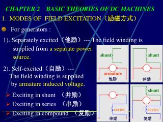
Commutation problems Armature reaction: The current supplied by rotor to the load, produces its own magnetic field that distorts the original magnetic field from the machine’s poles. This distortion of the machine’s flux as the load increases is called armature reaction and can cause two problems Neutral plane shift Flux weakening
Problems with commutation in real DC machines A two-pole DC machine: initially, the pole flux is uniformly distributed and the magnetic neutral plane is vertical. The effect of the air gap on the pole flux. When the load is connected, a current – flowing through the rotor – will generate a magnetic field from the rotor windings.
Problems with commutation –shift of neutral plane This rotor magnetic field will affect the original magnetic field from the poles. In some places under the poles, both fields will sum together, in other places, they will subtract from each other Therefore, the net magnetic field will not be uniform and the neutral plane will be shifted. In general, the neutral plane shifts in the direction of motion for a generator and opposite to the direction of motion for a motor. The amount of the shift depends on the load of the machine.
Problems with commutation in real DC machines The commutator must short out the commutator segments right at the moment when the voltage across them is zero. The neutral-plane shift may cause the brushes short out commutator segments with a non-zero voltage across them. This leads to arcing and sparkling at the brushes!
Problems with commutation in real DC machines 2) Flux weakening. Most machines operate at flux densities near the saturation point. At the locations on the pole surfaces where the rotor mmf adds to the pole mmf, only a small increase in flux occurs (due to saturation). However, at the locations on the pole surfaces where the rotor mmf subtracts from the pole mmf, there is a large decrease in flux. Therefore, the total average flux under the entire pole face decreases.
Problems with commutation in real DC machines 2. L di/dt voltages This problem occurs in commutator segments being shorten by brushes and is called sometimes an inductive kick. Assuming that the current in the brush is 400 A, the current in each path is 200 A. When a commutator segment is shorted out, the current flow through that segment must reverse. Assuming that the machine is running at 800 rpm and has 50 commutator segments, each segment moves under the brush and clears it again in 0.0015 s.
Problems with commutation in real DC machines The rate of change in current in the shorted loop averages Therefore, even with a small inductance in the loop, a very large inductive voltage kick L di/dt will be induced in the shorted commutator segment. This voltage causes sparking at the brushes.
Solutions to the problems with commutation Interpoles 1. Commutating poles or interpoles To avoid sparkling at the brushes while the machine’s load changes, instead of adjusting the brushes’ position, it is possible to introduce small poles (commutating poles or interpoles) between the main ones to make the voltage in the commutating wires to be zero. Such poles are located directly over the conductors being commutated and provide the flux that can exactly cancel the voltage in the coil undergoing commutation. Interpoles do not change the operation of the machine since they are so small that only affect few conductors being commutated. Flux weakening is unaffected. Interpole windings are connected in series with the rotor windings. As the load increases and the rotor current increases, the magnitude of neutral-plane shift and the size of Ldi/dt effects increase too increasing the voltage in the conductors undergoing commutation.
Solutions to the problems with commutation However, the interpole flux increases too producing a larger voltage in the conductors that opposes the voltage due to neutral-plane shift. Therefore, both voltages cancel each other over a wide range of loads. This approach works for both DC motors and generators. The interpoles must be of the same polarity as the next upcoming main pole in a generator; The interpoles must be of the same polarity as the previous main pole in a motor. The use of interpoles is very common because they correct the sparkling problems of DC machines at a low cost. However, since interpoles do nothing with the flux distribution under the pole faces, flux-weakening problem is still present.
Solutions to the problems with commutation (compensating winding) 2. Compensating windings The flux weakening problem can be very severe for large DC motors. Therefore, compensating windings can be placed in slots carved in the faces of the poles parallel to the rotor conductors. These windings are connected in series with the rotor windings, so when the load changes in the rotor, the current in the compensating winding changes too…
Solutions to the problems with commutation Rotor and comp. fluxes Pole flux Sum of these three fluxes equals to the original pole flux.
Solutions to the problems with commutation A stator of a six-pole DC machine with interpoles and compensating windings. pole interpole
The power-flow diagram On of the most convenient technique to account for power losses in a machine is the power-flow diagram. For a DC motor: Electrical power is input to the machine, and the electrical and brush losses must be subtracted. The remaining power is ideally converted from electrical to mechanical form at the point labeled as Pconv.
Equivalent circuit of a DC motor The armature circuit (the entire rotor structure) is represented by an ideal voltage source EA and a resistor RA. A battery Vbrush in the opposite to a current flow in the machine direction indicates brush voltage drop. The field coils producing the magnetic flux are represented by inductor LF and resistor RF. The resistor Radj represents an external variable resistor (sometimes lumped together with the field coil resistance) used to control the amount of current in the field circuit.
Equivalent circuit of a DC motor Sometimes, when the brush drop voltage is small, it may be left out. Also, some DC motors have more than one field coil… The internal generated voltage in the machine is The induced torque developed by the machine is Here K is the constant depending on the design of a particular DC machine (number and commutation of rotor coils, etc.) and is the total flux inside the machine. Note that for a single rotating loop K = /2.
Separately excited and Shunt DC motors Note: when the voltage to the field circuit is assumed constant, there is no difference between them… Separately excited DC motor: a field circuit is supplied from a separate constant voltage power source. Shunt DC motor: a field circuit gets its power from the armature terminals of the motor. For the armature circuit of these motors:
Shunt motor: terminal characteristic A terminal characteristic of a machine is a plot of the machine’s output quantities vs. each other. For a motor, the output quantities are shaft torque and speed. Therefore, the terminal characteristic of a motor is its output torque vs. speed. If the load on the shaft increases, the load torque load will exceed the induced torque ind, and the motor will slow down. Slowing down the motor will decrease its internal generated voltage (since EA = K), so the armature current increases (IA = (VT – EA)/RA). As the armature current increases, the induced torque in the motor increases (since ind = KIA), and the induced torque will equal the load torque at a lower speed .
Shunt motor: terminal characteristic Assuming that the terminal voltage and other terms are constant, the motor’s speed vary linearly with torque. However, if a motor has an armature reaction, flux-weakening reduces the flux when torque increases. Therefore, the motor’s speed will increase. If a shunt (or separately excited) motor has compensating windings, and the motor’s speed and armature current are known for any value of load, it’s possible to calculate the speed for any other value of load.
Shunt motor: terminal characteristic – Example Example : A 50 hp, 250 V, 1200 rpm DC shunt motor with compensating windings has an armature resistance (including the brushes, compensating windings, and interpoles) of 0.06 . Its field circuit has a total resistance Radj + RFof 50 , which produces a no-load speed of 1200 rpm. The shunt field winding has 1200 turns per pole. a) Find the motor speed when its input current is 100 A. b) Find the motor speed when its input current is 200 A. c) Find the motor speed when its input current is 300 A. d) Plot the motor torque-speed characteristic.
Shunt motor: terminal characteristic – Example The internal generated voltage of a DC machine (with its speed expressed in rpm): Since the field current is constant (both field resistance and VT are constant) and since there are no armature reaction (due to compensating windings), we conclude that the flux in the motor is constant. The speed and the internal generated voltages at different loads are related as Therefore: At no load, the armature current is zero and therefore EA1 = VT = 250 V.
Shunt motor: terminal characteristic – Example a) Since the input current is 100 A, the armature current is Therefore: and the resulting motor speed is: b) Similar computations for the input current of 200 A lead to n2 = 1144 rpm. c) Similar computations for the input current of 300 A lead to n2 = 1115 rpm. d) To plot the output characteristic of the motor, we need to find the torque corresponding to each speed. At no load, the torque is zero.
Shunt motor: terminal characteristic – Example Since the induced torque at any load is related to the power converted in a DC motor: the induced torque is For the input current of 100 A: For the input current of 200 A: For the input current of 300 A:
Shunt motor: terminal characteristic – Example The torque-speed characteristic of the motor is:
Shunt motor: Speed control There are two methods to control the speed of a shunt DC motor: • Adjusting the field resistance RF (and thus the field flux) • Adjusting the terminal voltage applied to the armature • Adjusting the field resistance • Increasing field resistance RF decreases the field current (IF = VT/RF); • Decreasing field current IF decreases the flux ; • Decreasing flux decreases the internal generated voltage (EA = K); • Decreasing EA increases the armature current (IA = (VT – EA)/RA); • Changes in armature current dominate over changes in flux; therefore, increasing IA increases the induced torque (ind = KIA); • Increased induced torque is now larger than the load torque load and, therefore, the speed increases; • Increasing speed increases the internal generated voltage EA; • Increasing EA decreases the armature current IA… • Decreasing IA decreases the induced torque until ind = loadat a higher speed .
Shunt motor: Speed control The effect of increasing the field resistance within a normal load range: from no load to full load. Increase in the field resistance increases the motor speed. Observe also that the slope of the speed-torque curve becomes steeper when field resistance increases.
Shunt motor: Speed control 2. Changing the armature voltage This method implies changing the voltage applied to the armature of the motor without changing the voltage applied to its field. Therefore, the motor must be separately excited to use armature voltage control. Armature voltage speed control
Shunt motor: Speed control • Increasing the armature voltage VA increases the armature current (IA = (VA - EA)/RA); • Increasing armature current IA increases the induced torque ind (ind = KIA); • Increased induced torque indis now larger than the load torque load and, therefore, the speed ; • Increasing speed increases the internal generated voltage (EA = K); • Increasing EA decreases the armature current IA… • Decreasing IA decreases the induced torque until ind = loadat a higher speed . Increasing the armature voltage of a separately excited DC motor does not change the slope of its torque-speed characteristic.
Shunt motor: Speed control If a motor is operated at its rated terminal voltage, power, and field current, it will be running at the rated speed also called a base speed. Field resistance control can be used for speeds above the base speed but not below it. Trying to achieve speeds slower than the base speed by the field circuit control, requires large field currents that may damage the field winding. Since the armature voltage is limited to its rated value, no speeds exceeding the base speed can be achieved safely while using the armature voltage control. Therefore, armature voltage control can be used to achieve speeds below the base speed, while the field resistance control can be used to achieve speeds above the base speed. Shunt and separately excited DC motors have excellent speed control characteristic.
Shunt motor: Speed control For the armature voltage control, the flux in the motor is constant. Therefore, the maximum torque in the motor will be constant too regardless the motor speed: Since the maximum power of the motor is The maximum power out of the motor is directly proportional to its speed. For the field resistance control, the maximum power out of a DC motor is constant, while the maximum torque is reciprocal to the motor speed.
Shunt motor: Speed control Torque and power limits as functions of motor speed for a shunt (or separately excited) DC motor.
Motor types: The permanent-magnet DC motor A permanent magnet DC (PMDC) motor is a motor whose poles are made out of permanent magnets. Advantages: • Since no external field circuit is needed, there are no field circuit copper losses; • Since no field windings are needed, these motors can be considerable smaller. Disadvantages: • Since permanent magnets produces weaker flux densities then externally supported shunt fields, such motors have lower induced torque. • There is always a risk of demagnetization from extensive heating or from armature reaction effects (via armature mmf).
Motor types: The permanent-magnet DC motor A comparison of magnetization curves of newly developed permanent magnets with that of a conventional ferromagnetic alloy (Alnico 5) shows that magnets made of such materials can produce the same residual flux as the best ferromagnetic cores. Design of permanent-magnet DC motors is quite similar to the design of shunt motors, except that the flux of a PMDC motor is fixed. Therefore, the only method of speed control available for PMDC motors is armature voltage control.
Motor types: The series DC motor A series DC motor is a DC motor whose field windings consists of a relatively few turns connected in series with armature circuit. Therefore: (5.75.1)
Series motor: induced torque The terminal characteristic of a series DC motor is quite different from that of the shunt motor since the flux is directly proportional to the armature current (assuming no saturation). An increase in motor flux causes a decrease in its speed; therefore, a series motor has a dropping torque-speed characteristic. The induced torque in a series machine is Since the flux is proportional to the armature current: where c is a proportionality constant. Therefore, the torque is Torque in the motor is proportional to the square of its armature current. Series motors supply the highest torque among the DC motors. Therefore, they are used as car starter motors, elevator motors etc.
Series motor: terminal characteristic Assuming first that the magnetization curve is linear and no saturation occurs, flux is proportional to the armature current: Since the armature current is and the armature voltage The Kirchhoff’s voltage law would be