Download
1 / 23
230 likes | 379 Views
FEE + ROC cooling. S. Popescu CERN, U. Frankenfeld, H.R. Schmidt GSI. Lauda System. PUMP. Lauda System. IROC in Thermal Box + 4 FEC (3.1). Inside: Sensors on pad plane. T8. T8. T9. T10. T13. T7. T5. T6. T11. T12. IROC. ~10cm. ~10cm. T14. T15. FEC.

E N D
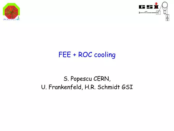
FEE + ROC cooling S. Popescu CERN, U. Frankenfeld, H.R. Schmidt GSI
Lauda System PUMP Lauda System IROC in Thermal Box + 4 FEC (3.1) Inside: Sensors on pad plane T8 T8 T9 T10 T13 T7 T5 T6 T11 T12 IROC ~10cm ~10cm T14 T15 FEC Separate cool. circuits for chamber + FEC Sensors on FEC cool. plates TPC meeting
Thermal Box T=21 ˚C Cooling In IN Cooling Out FEC PS Chamber cool. T=21˚C Temp sensors TPC meeting
IROC Chamber Cooling circuit T9 T10 T11 T12 4 FEC (3.1) ~10.5 W/card (3.2: ~6.9 W/card) Input Cooling circuit Output Cooling circuit TPC meeting
ELMB PT1000 two wire sensors connected Can Bus port TPC meeting
Cooling plate Inner screws T14 TPC meeting
Single card w/o inner screws LV OFFLV ON ΔT~5.5 ˚C ΔT cooling plates TPC meeting
Card w/o inner screws in set-up LV ONLV OFF ΔT~4 ˚C ΔT cooling plates TPC meeting
Single card with all screws All screws in ΔT cooling plates ΔT ~1 ˚C TPC meeting
Chamber cooling Cc offCooling circuit on ~ 50 minutes chamber Pad TPC meeting
All circuits 21˚C Chamber 21 -> 19.5 ˚C Chamber cooling pads ΔT ~1.5 ˚C chamber chamber cooling TPC meeting
All circuits 21˚C Gradients on the pad plane Chamber cooling pad under FEC pad ΔT ~0.08 ˚C TPC meeting
Heat transfer to pad plane Pad under FEC LV OFFLV ON ΔT ~0.18˚C Δt ~ 30 min TPC meeting
Chamber 21˚C FEE cooling 19˚C Thermal box 21˚C Heat transfer with cable LV ON | LV OFF pad Heat transfer: ~0.19˚C pad under FEC TPC meeting
Chamber 21˚C FEE cooling 19˚C Thermal box 21˚C Heat transfer without cable LV ON | LV OFF pad Heat transfer: ~0.15˚C pad under FEC TPC meeting
Compensation 19-24 ˚C LV OFF LV ON LV OFF FEC cool:T=19 ˚CT=24 ˚C T=19 ˚C T=24 ˚C TPC meeting
Temperature cooling FEE 19->24 ˚C pad under FEC ΔT ~ 0.14˚C pad TPC meeting
Compensate: Switching ON pad under FEC ΔT ~ 0.05˚C pad TPC meeting
Compensate: Switching OFF FEC cool. temperature (scaled) pad under FEC pad TPC meeting
Compensate: Switching OFF pad under FEC ΔT ~ 0.06˚C pad TPC meeting
Compensation (16-21˚C) LV OFF LV ON LV OFF FEC cool: T=21˚C T=16˚C T=21 ˚C TPC meeting
Compensation (16-21˚C) LV ON LV OFF pad under FEC ΔT ~ 0.05˚C pad TPC meeting
Summary + Conclusion • Setup with 4 FEC (Ver. 3.1) 10.5 W per Card • Heat transfer between both sides of cooling plates thru screws: Single sided cooling? • Chamber circuit for stabilization not compensation • Time constant Δt ~ 50 min • Heat transfer FEC -> pads • Time constant Δt ~ 30 min • ~0.19 ˚C with cable • ~0.14 ˚C without cable • Compensation with Cooling temperature per sector • Test setup: Compensation on pads with ΔT ~ 0.05 ˚C TPC meeting