Download
1 / 16
160 likes | 242 Views
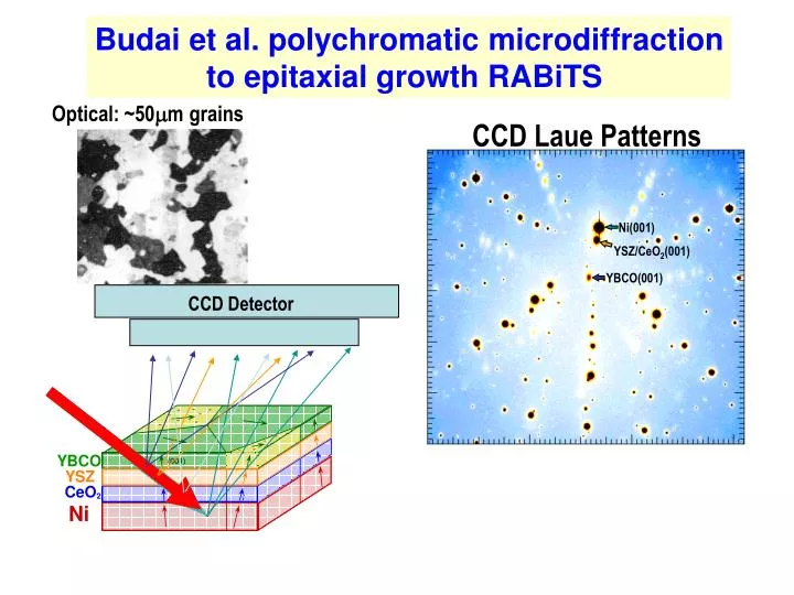
CCD Laue Patterns. Ni(001). YSZ/CeO 2 (001). YBCO(001). CCD Detector. Budai et al. polychromatic microdiffraction to epitaxial growth RABiTS. Optical: ~50 m grains. 900. 600°C. 450°C. 900. 800. 700. 700. 600. 500. Y (pixels). Y (pixels). 500. 400. 300. 300. 200. Ni. •.

E N D
CCD Laue Patterns Ni(001) YSZ/CeO2(001) YBCO(001) CCD Detector Budai et al. polychromatic microdiffraction to epitaxial growth RABiTS Optical: ~50mgrains
900 600°C 450°C 900 800 700 700 600 500 Y (pixels) Y (pixels) 500 400 300 300 200 Ni • Ni • CeO CeO 100 2 2 100 200 300 400 500 600 700 800 900 1000 200 300 400 500 600 700 800 900 1000 X (pixels) X (pixels) Relative CeO2orientation depends deposition temperature High temperature growth: Crystallographic tilt towards ^ Tiltincreases monotonically with miscut Low temperature growth: Small, ~biased tilts
Ni CeO2 YBCO ^ 5.3° Microbeam enables combinatorial measurements on real samples 730 mm Budai JD, Yang WG, Tamura N, Chung JS, Tischler JZ, Larson BC, Ice GE, Park C, Norton DP NATURE MATERIALS 2 (7): 487-492 JUL 2003
Important questions remain • Why does Jcdecrease for thick samples? • Why does mosaic on single Ni substrate grain differ dramatically between samples?
How grain boundary/polycrystal networks interact - a major materials opportunity 21st century • What are the constitutive equations at grain boundaries? • How do they change with boundary type • What are ideal microstructures? • How do different networks evolve during processing and in service? • How can grain boundary distributions be controlled? • Grain boundary engineering Essential for nanophase and advanced layered materials
UVW Misorientation: rotation of θ angle about a common axis UVW θ Lattice 1 Lattice 2 Unprecedented precision addresses long-standing issues/ tests CSL models • CSL low-energy boundaries share lattice sites • denotes inverse fraction of shared sites • Theory: misorientation increases as decreases • Measured misorientation increase with • Grain boundary normals • Ideal directions should have lower energy • Faceting may remove energy advantage Morphology of Ni triple junction
Significant statistical information emerging Total: 70 About 50% are CSLs, and 20% are found to be tilt, twist or having low-index in both grains. Open questions: 1. Why and how are the deviations from ideal CSL model as type increases? 2. Are there residual strains imposed near the deviated CSL boundaries? 3. Any difference of CSLs between near or below sample surface? 4. …………
B C A B B A C A C Three Dimensional Morphology of Triple Junction 3-D mapping Sample surface height contour Misorientaion angles: A-B: 16.572° B-C: 12.907° C-A: 5.538° surface step between two grains
Polycrystalline grain structure can now be measured nondestructively in 3D-submicron resolution-meso scale
5 µm Thermal Grain Growth in Hot-Rolled Aluminum 1 µm pixels, Boundaries: 5° & 20° Anneal 250ºC, 1 hr Anneal 350ºC, 1 hr Anneal 355ºC, 1 hr Anneal 360ºC, 1 hr • GB motions include both high-angle and low-angle boundaries • Complete and detailed 3D evolution needed for validation of theories.
Elastic strain key driving force-Monochromatic DAXM measures intra-granular elastic strain • Local strain-even in single crystal • Ultra-high precision local orientations • Independent of grain orientation • Phase sensitive Revolutionizes ability to study materials
<112> <111> Lattice Rotation Map 5.1x10¹⁰/cm2 <110> • <111> Cu100 mN Indent Force69 µm Indent Radius Indent Tip A 5 o Probe Geometry 40 m Nanoindent in single crystals provides major insights into 3D deformation/modeling • Deformation boundary conditions completely known/ volume modelable • Best models predict some features not others-highly reproducible • Single, bi-crystal, or polycrystal • Strain-gradient models directly testable Dislocation Density Map
In-situ tensile deformation polycrystal finds intra-granular variations • Dramatic changes in deformations within single grain • Consistently large rotations near surface • Plastic and elastic deformation measured • Essential information for understanding mechanisms • Extensive sample characterization required for full boundary conditions Proposed research • Full boundary conditions • Low deformation • Integrate theory Tensile deformed poly-Ni
To achieve potential and meet emerging demand - new microbeam lines and hardware proposed Multiplexed 3D polychromatic diffraction-center for mesoscale research- -BM -Operated by APS -Greater general user access Spatial resolution 50nm10nm Accelerated 3D characterization 100-1000x - Multiple wire/coded aperture - Faster detectors (GE detectors)
Summary: - important emerging technique • Cannot meet demand with existing facilities • Addresses long-standing issues with fundamentally new approach • Wide applicability
Team of ORNL scientists involved • Gene Ice- Co-principle investigator, x-ray optics • Bennett Larson- Co-principle investigator-3D deformation/nanoindentation • John Budai-Epitaxial films and 3D grain growth • Jonathan Tischler-Mesoscale measurements and computer analysis (CMSD - APS Site) • Wenge Yang-Mesoscale deformation using nanoindentation (Guest Scientist- APS Site) • Wenjun Liu-Grain boundary networks (Post Doc-APS Site) • Judy Pang-in-situ 3D polycrystalline deformation Important support from APS-differentially deposited elliptical mirrors and beam stabilization