Download
1 / 30
340 likes | 607 Views
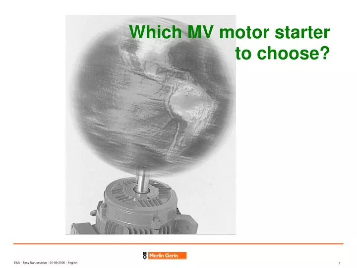
Which MV motor starter to choose?. starter. Network. Load. Motor. The MV starter and motor are the links between the electrical network and the mechanical load. Motor. Load. Protection. Network. Overcurrent Thermal (I²t) rotor Thermal (Pt100) stator.

E N D
starter Network Load Motor The MV starter and motor are the links between the electrical network and the mechanical load
Motor Load Protection Network Overcurrent Thermal (I²t) rotor Thermal (Pt100) stator The motor starter must be designed to limit the constraints to the network, the motor and the load The type of motor starter will influence the perturbations on the network the mechanical strength to the mechanical load the starting torque on the shaft The protection will protect the motor
The network has constraints • Acceptable inrush current • Acceptable starting undervoltage • Acceptable power factor • short circuit withstand • Acceptable harmonics
The load has constraints • Resistant torque curve • Starting inertia • Acceptable mechanical stress • operating conditions • Starting time • number of starts • automatic starting • operating cycle • overload • locked rotor current • deceleration control • ........
The motor-starter must be designed to control, protect and supervise the motor for maintenance • Motor control: local or remote; automation.... • Electrical motor protection • short circuit • under-voltage • ........ • Preventive protection • temperature through thermal image or sensors • bearing vibration sensors • moisture • derating for altitude • ......... • The design of the motor starter should decrease the number of spare parts.... • .........
The most common motor: asynchronous motor phase 3 phase 2 phase 1 • the 3 windings of the stator are placed at 120° and are fed by the service voltage • these 3 coils create a rotating magnetic field around the axis of the stator • this magnetic field creates a current in the rotor • the rotation of the rotor N is lightly slower as the magnetic field one Ns • There are 2 types of asynchronous motors • single or double cage motors (rotor is short circuited) • slip ring rotor motor (resistance of the rotor can be modified by introducing external resistances) 120°
Influence of the service voltage on the motor torque Torque V"s > V's V's >Vs starting torque Vs resistant torque Ns N (speed) acceleration torque The lower the voltage; the lower the motor torque If the motor torque is lower than the resistant torque the motor does not start
Asynchronous motor double cage single cage rotor deep slot rotor motor low slightly higher starting torque from 0.6 to 1 Tr from 0.8 to 1.2 Tr around 2 to 2.2 Tr maximum torque around 2 to 2.2 Tr (slightly higher for deep slots) starting current from 4.5 to 5.5 Ir from 5 to 6.5 Ir excellent mechanical and electrical robustness simplicity of design no brushes relatively low power factor 0.8 to 0.9 on full load if asynchronous installed motor power is high reactive, power compensation may be required these motors are ideal for intensive use and hazardous environments
T R= rotor resistance Rr ’ > T max Ts T load N Asynchronous slip ring rotor motor • the impedance of the rotor winding can be modified by introducing external resistances. • by decreasing external resistance on starting (from Rr" to R), the characteristic of the torque is translated and the starting torque adapted to the torque of the machine. Rr ’' >
Synchronous motor • The main differences with asynchronous motors are: • their constant speed (synchronous speed) • the rotor circuit supplied with Dc • the power factor which may be set by the exciting current • In a conventional synchronous motor controller • the DC power is applied from an external source • brushes and slip rings carry the current to the field winding • A brushless synchronous motor • it generates its own DC power for its field • the amount of DC power is controlled through induction • low current DC power applied from the controller
Load torque curves of machines compressor
Starting conditions:motor torque must always be greater than the load torque the motor does not start the motor starts running point
Some of the different types of MV motor starter • Full voltage on the stator or direct on line • FVNR or DOL • Reduced Voltage through reactance • Reduced Voltage through auto-transformer • RVAT • Reduced Voltage trough soft starter • RVSS (SoftStart)
Motor Load Network Protection Direct stator starting on full voltage (FVNR) • Locked rotor current on starting is around 4 to 7 In depending on motor characteristics • starting time of 1 to 10 seconds depending on the moment of total inertia (motor + machine), motor torque and load torque • the network must be able to withstand the starting current without disturbing other loads • the machine being driven must be able to withstand the mechanical impact due to the motor torque • This mode is very popular (simple, robust, not expensive)
Motor Load I T/Tn Id/In T L1shunted Tmax I L1shunted 4 T with L1 2 I with L1 2 Tr If(Tr) 1 In resistant torque N N N1 Nn N1 Nn Reduced voltage by reactance L1 Network Protection • This starting mode reduces current inrush on the network in the simplest manner. Since the motor starting torque is low, the machines being driven must have a relatively low torque during star up: compressors; centrifugal pumps; converter sets....
Ct1 Ct2 Motor Load Ct3 I T/Tn Id/In Ct2 and Ct3 closed Tmax Ct2 closed 4 Ct2 and Ct3 closed Ct1 and Ct2 closed 2 Ct2 closed 2 Ct1 and Ct2 closed Tr If(Tr) 1 In resistant torque N N N1 Nn N1 Nn Reduced voltage by auto-transformer • This system is recommended for high power motors. It has the advantage of not dissipating energy. • It can be used to obtain, for the same decrease in current, less reduction in torque than with the reactor starter. Protection Network N1
First stage: CT1 must be closed before CT2. CT1 and CT2 are closed CT3 is open CT2 and CT3 are closed Second stage: CT1 is opened CT2 remains closed CT3 remains open Third stage: CT3 is closed CT2 remains closed CT1 remains open CT1 is opened CT2 are closed CT1 and CT2 are closed Auto Transformer starting Sequence First stage : the motor is starting with reduced voltage. Second stage: the motor is running in series with part of the autotransformer winding. The motor is always supplied during the second stage, when CT1 is open. Third stage: the motor runs at full voltage.
Motor Load Reduced voltage by Soft Starter Soft starter Protection • The soft starter is an solid state device which controls the starting period of the motor • depending on the application several settings are possible. • When the motor is running a contactor shunts the electronic starting module. • Advantages • Reduction of starting current • Reduction of starting torque and mechanical shock ( the torque may be adjusted to the resistant torque) • smooth acceleration and deceleration of the motor • It is a solution when auto-transformer motor starter is not possible. But it is not a variable speed starter • Only the price limits the use of the Soft Starter Network
Soft starter setting: different possibilities • current limitation setting • torque control setting • mix of both • ........ • deceleration possibilities
Motor Load I and Torque fix frequency limited T= Tn * (In / Il)2 T/Tn 2 Is/In ( ) U T=function Tmax Un n 4 U n 2 U Limit of the starting current 5 8 , Il 0 2 n Tsn U Tr 6 , 0 If(Tr) 1 In Tlimited resistant torque N N N1 Nn N1 Nn Soft starter setting: current limitation Soft starter Protection Network The voltage is increased until the starting current reaches the limit, then voltage is maintained at this current, and then the voltage is increased again up to the service voltage
Motor Load T I and N and T C speed ramp fonction of torque ramp torque control x In I starter I1 U starter=> F Un Nn In Tn Tn U1 T1 resistant torque resistant torque t t t1 F1 T1 = k. I1 t1 Soft starter setting: torque control Soft starter Protection Network The voltage is set to have a motor torque just above the resistant torque. If the resistant torque is constant the starting voltage may be close the full voltage; the inrush current maybe close the direct on line inrush current
Motor Load Soft starter: normal setting Network Soft starter Protection The initial torque setting applies sufficient voltage to the motor to cause the motor shaft to begin to turn. This voltage is gradually increased overtime (as per the ramp time setting) until either: the motor accelerates to full speed the ramp time expires a current limit is reached. If the motor has not reached the full speed at the end of the ramp setting, the current limit setting will proportionally control the maximum output torque The current remains limited for as long it takes the motor to accelerate to full speed. When the motor reaches full speed and the current drops to running level, the by pass contactor shunts the soft starter module.The motor is now running at the full voltage.
Network Soft starter Protection Motor Load Soft starter setting: deceleration The starter may be used to control the deceleration by slowly reducing the voltage to the motor upon initiating a stop command the most common application for the decel feature is pumping application, in which a controlled stop prevents water hammer and mechanical damage to the system.
VSD specific Starting mode selection table yes - deceleration control ? no - the drive between motor and load is able to withstand the mechanical stress of a direct on line start no yes - constant torque with high starting torque as crushers, grinders, mixers ...... yes no Network requirement Investment Increase - accepts full starting current? - accepts starting voltage drop? no yes no no no -accepts the starting reactive consumption power? yes yes yes - accepts the current oscillation during an open transition? no yes no - accepts the harmonics during the starting period yes FVNR RVAT RVSS
Rating Current of the contactor • The power of a motor is the mechanical power.To determine the rating of the contactor we have to calculate the full load current of the motor. • The electrical power of the motor will be the mechanical one divided by the efficiency. • Is= Pm/(Us x V3 cosj*h) • where • Pm: power of the motor • Us service voltage • cosj power factor • h efficiency of the motor • Ir contactor > Is * k (k derating factor) • if the altitude <1000m k=1