Download
1 / 59
590 likes | 750 Views
University of Arizona Student Satellite Project “UASat”. Spring 2000 Formal Review April 27, 2000. Purpose of Spring 2000 Review. End of Semester Review of SSP Preparation for UASat Preliminary Design Review (PDR) Gathering Team-Level Information Provide System-Level Overview

E N D
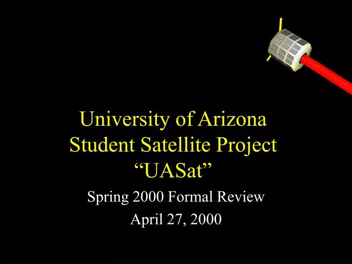
University of Arizona Student Satellite Project“UASat” Spring 2000 Formal Review April 27, 2000
Purpose of Spring 2000 Review • End of Semester Review of SSP • Preparation for UASat Preliminary Design Review (PDR) • Gathering Team-Level Information • Provide System-Level Overview • Seek Advice and Guidance
Presentation Schedule • 5:00- Project Manager Overview & Introduction • 5:20- Science • 5:50- Laser Communications • 6:10- Guidance, Navigation & Control • 6:30- Break • 6:40- Systems Integration • 7:00- Mechanical, Structures & Analysis • 7:20- Data & Command Handling • 7:40- Power Generation & Distribution
Purpose of SSP 1. A hands-on experience through team work on a complex system with an objective 2. A needed channel for many students to gain self-confidence & employable skills 3. An example of intercollegiate, inter-departmental, and interdisciplinary collaboration 4. An avenue to enhance beneficial interactions among university and community 5. A test-bed for innovative ideas in a wide variety of areas
Sprite & Lightning Detection Photometry of Bright Stars Laser Communication Experiment UASat Mission
Purpose of SSP 1. A hands-on experience through team work on a complex system with an objective 2. A needed channel for many students to gain self-confidence & employable skills 3. An example of intercollegiate, inter-departmental, and interdisciplinary collaboration 4. An avenue to enhance beneficial interactions among university and community 5. A test-bed for innovative ideas in a wide variety of areas
Purpose of SSP 1. A hands-on experience through team work on a complex system with an objective 2. A needed channel for many students to gain self-confidence & employable skills 3. An example of intercollegiate, inter-departmental, and interdisciplinary collaboration 4. An avenue to enhance beneficial interactions among university and community 5. A test-bed for innovative ideas in a wide variety of areas
SSP needs the support from the four vertices: UA, Local Community, Industry, & Gov’t Human resources Space & facilities Operational Support SpaceGrant UA SSP Internship. Components Sub-systems Technical expertise Testing facilities NASA NSF HES launch Industry Curriculum development Local Community Scholarships, Mentorships, Donations KCH21.VI.1998
Criteria for Success • Minimum Criteria • Continuous flow of graduates with experience. • Ultimate accomplishment • Delivery of UASat for NASA launch and successful operation in flight, followed by scientific and technological return.
Management • Project Manager- Jon Alberding, BME • Recruiting, Fundraising, Resources, Administration, Systems Integration & Intra-Team Communication • Project Assistant- Ether Adnan, MIS • Project Communication, Administration, Account Management • System Engineer- Christiano Adabi, SIE • System Documentation • Interfaces • Budgets • Design Database
Management (Cont.) • Project Mentors • Dr. K. C. Hsieh, Physics • Dr. Hal Tharp, ECE (sabbatical) • SI Mentor • Dr. Terry Bahill, SIE • Administrative Mentor • Susan Brew, SpaceGrant
Current UASat Schedule • Requirements Review (Completed 8/18/98) • Preliminary Design Review (Late ‘00, Early ‘01) • Critical Design Review (Spring ‘02) • Mission Readiness Review (Fall ‘03) • Delivery to NASA (Spring ‘04)
Program Management group works with Teams Program Management group forms Preliminary Gantt chart Negotiate Final Schedule (TL, Mentor, PM, SE) Teams review IMAGE PDR Teams review PDR outlined by System Engineer/Project Manager Negotiate Final Schedule (TL, Mentor, PM, SE) UASat PDR Preparation
Management-Level PDR Requirements • Risk Management • Schedule Control • No real means of control • Need for Risk Mitigation Strategy • Technical Oversight Group • Better Communication about Schedule Slip • Quantitative Evaluation of Schedule Performance • What To Do If Slippage Occurs?
Management-Level PDR Requirements • Cost Control • Inherent Controls • Student Project • Students Build Some Components/Subsystems • Knowledge of Actual Costs for Bought Items • Cost Tracking Strategy & Plan for When Reserves Utilized • Descoping • Decision Tree, Options & Consequences • Performance Assurance Implementation Plan (PAIP)
Questions on Management • How to retain Lower-Division Students? • How to have a Risk Mitigation Strategy with limited resources & maintaining Educational Requirements? • How to acquire needed resources? • How to formulate a plan to cost-effectively acquire needed components? • How to implement a PAIP?
How to Contact SSP • SSP HQ • Physics and Atmospheric Sciences, Room 569 • Phone • (520) 621-2574 • Email: • ssp-admin@uasat.arizona.edu • World Wide Web • http://uasat.arizona.edu
“The Student Satellite Project at the University of Arizona is the best evidence I have discovered anywhere of the creative initiative of Americans committed to the Space Program, which has been an important part of my life for forty years. When I joined JPL as a young engineer in 1958, soon after the launch of America's first satellite, the adventure of space exploration had captured the imagination of young people all over America, and there was no bureaucracy to slow us down. The new NASA in 1998 recognizes the importance of youthful energy and innovative capacity, and welcomes such initiatives as the SSP. This is a very exciting development, heralding as new day for both NASA and our students. They have done their part, with the encouragement of the University of Arizona. Now it is time for the community to step up to the challenge of demonstrating that all of Arizona stands behind this incredible initiative of the young men and women of the SSP who are reaching beyond the skies.” Peter Likins, June 17, 1998.
Presentation Schedule • 5:00- Project Manager Overview & Introduction • 5:20- Science • 5:50- Laser Communications • 6:10- Guidance, Navigation & Control • 6:30- Break • 6:40- Systems Integration • 7:00- Mechanical, Structures & Analysis • 7:20- Data & Command Handling • 7:40- Power Generation & Distribution
UASat: Guidance, Navigation, and ControlsPresented by Brian Shucker and Martin Leblhttp://uasat.arizona.edu/gnc
Team Members: Greg Chatel (AME) Barry Goeree (AME) Andreas Ioannides (Phys) Gregg Radtke (ME) Team Mentor: Dr. Fasse (AME) Marissa Herron (AME) Martin Lebl (CSc) Brian Shucker (CSc/Math) Roberto Furfaro (AME) GNC Team Members
GNC Subsystem Requirements • Science and Technical Objectives • Lightning and Sprite observation • requires attitude knowledge with respect to Earth • requires horizon pointing • Stellar Photometry • requires attitude knowledge with respect to the stars • requires inertial pointing • Laser Communication System • requires attitude knowledge with respect to Earth • requires ability to perform groundstation tracking slew maneuver • Power Generation • requires attitude knowledge with respect to Sun • requires inertial pointing • Three axis control required
Sensors • Sensors Used • Attitude Sensors: Magnetometer, Coarse Sun Sensor • Spatial Sensor: GPS • Rate Sensor: Integrating Rate Gyros • Sensor Measurement Rates • Power vs. Accuracy Trade-Off • Optimization Technique TBD
-- Discrete Measurement Updates -- Continuous Dynamic Propagation Models Extended Kalman Filter Block Diagram t k Out to controller u In from instruments State Model t State Update i.c. Gain Update t k Covariance Update Covariance Model u t i.c.
The Kalman Filter • State Variable: • Measurement Updates • Gain Matrix: • State Update: • Covariance Update: • Dynamic Propagation Between Measurements • Data from rate gyros will be numerically integrated • Equations of motion are excluded to simplify the analysis
Magnetometer • Advantages: • Can be used throughout orbit (sunside and darkside) • Low power • Relatively affordable sensor • Disadvantages: • Cannot be used with the magneto torquers on • Only so much precision can be achieved using it
GPS board – Space Rated • Space rated board • Advantages: • Proven Heritage Design • Radiation Hardened • Disadvantages: • Expensive
GPS board -- Terrestial • Terrestial board • Advantages: • Relatively Inexpensive • Disadvantages: • Needs modification to the firmware by manufacturer • May need Radiation shielding depending on where it is mounted • Obviously still non-heritage design (only flew on ASUSAT, but never been turned on before ASUSAT expired.)
Coarse Sun Sensor • Sensor implemented using the solar panels, and additional photo diodes to give complete coverage. • Only a course sensor for the power generation mode
Coarse Sun Sensor • Advantages: • Inexpensive design • Very low power • Disadvantages: • Only works on the sun side • Only useful for determining the sun vector for power generation
Current Status • Theory • Kalman Filtering is understood • Main reference: Lefferts, Markley and Shuster (1982) • Sensor models are not complete • Matlab Code • Most equations are coded • Integration with other modules • Documentation • Tech. Note
Current Endeavors • Finish sensor modeling (h(), H) • Further develop & test Matlab code • Get it running and integrated with other systems • Refine estimates to get more realistic numbers • Generate plots and graphs to obtain pointing accuracy • Look into what would deployable solar panels allow us to do in terms of additional sensors, and what changes to the current design would it necessitate.
Open Issues & Concerns • Can we meet the accuracy requirements? • We won’t know until the simulation is complete. • Possibilities for improving accuracy • Add sensors: GPS attitude estimation system (GPS Compound Eye), low power Star tracker • Adjust sensor rates • Change the dynamic model to include equations of motion
What if we go to deployable solar panels ? • Need the Coarse Sun Sensor to be implemented solely by photo diodes • Have enough power for additional sensors: • GPS compound eye: • Works both sunside and darkside • Low Cost Start Tracker • Greatly increases our pointing accuracy
z h i Satellite n Direction of Perigee w y W Line of Nodes x Vernal equinox Kinematics
e4,rw e2,rw e3,rw x e1,rw Attitude Control: Reaction Wheels • Set of 4 miniature reaction wheels used for primary control z y
+ + + Dynamics and State Estimation Wheel Speed Management Pseudo Inverse Elastic Term Viscous Term Model-based Compensation Controller Block Diagram
Magnetic Torquers • Student designed and built • Used for momentum dumping and detumbling • Free-air coil design selected • Simplest, least costly design • Linear response to input current simplifies control requirements. • Possible issues with stray magnetic fields • Three required
Coil Design Formulae • Moment equation: • Mass and wire size: • Power, current, voltage and resistance:
Total Mass vs. Power Consumption Specifications Dipole moment of 5 Am2 Power consumption of 0.3 W 16 mA at 20 V Uses 32 gauge square magnet wire Total mass of 3 kg Design Optimization mass [kg] Power [watts]
Mounting Possibilities • Two ideas • Designed to fit within side beam • Wrapped into groove on exterior of satellite • Three coils form mutually perpendicular axes
Momentum Dumping Control Algorithm • The approach is to consider both the need and efficiency of dumping at a particular time. • Use change in angular momentum to estimate direction of the earth’s magnetic field in the absence of magnetometer reading.
Theory • Dipole moment calculations • Need and efficiency calculations
Start Conditions Stop Condition Conditions for Torquer Activation Need Detumbling HMax Start HStop Stop H0 • Velocity Restriction BStop BMax Efficiency
Current Status • Have opted for a torque coil design • Remaining hardware work is in mounting details. • Need to purchase or build amplifiers • Some fine tuning of momentum dumping control constants may be necessary.
Attitude Control Simulations • Attitude dynamics and orbital kinematics are simulated. • Magnetic field is modeled • The control laws are sampled at 4Hz. • The aerodynamic drag torques are modeled. Solar pressure, gravity gradient and residual magnetic moment are not modeled. • The reaction wheels models include: Coulomb and viscous friction, limited torque capability (7.4·10-3 Nm), misalignment (4o), uncertainty in gain (10%) and uncertainty in inertia (4%). • The satellite core model includes: uncertainty in the moments of inertia (5%) and principal axes of inertia (4o).
-3 x 10 5 4.5 4 3.5 3 2.5 2 1.5 1 0.5 0 0 200 400 600 800 1000 1200 Telescope axis pointing error Pointing error (degrees) Time (s)