Download
1 / 83
2.35k likes | 4.23k Views
Tutorial on Chemical Mechanical Polishing (CMP). Ara Philipossian Intel Corporation 1999 Arizona Board of Regents for The University of Arizona. Outline of the Tutorial. Section A: Overview Generalized schematics of CMP and Post-CMP Clean Current CMP environment Evolution of CMP

E N D
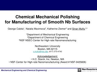
Tutorial onChemical Mechanical Polishing (CMP) Ara Philipossian Intel Corporation 1999 Arizona Board of Regents for The University of Arizona
Outline of the Tutorial • Section A: Overview • Generalized schematics of CMP and Post-CMP Clean • Current CMP environment • Evolution of CMP • The CMP Module • The CMP Infrastructure • Section B: Polishing equipment trends • Section C: Polishing process issues • Section D: Consumables (pads & slurries) • Quality issues • Factors affecting productivity • Critical pad and slurry parameters
Outline of the Tutorial • Section E: Industry - University Gaps • Section F: Environmental Health and Safety (EHS) considerations • Section G: Slurry fluid dynamics • Section H: Slurry re-use • Section I: Post-CMP cleaning
Schematic Diagram ofChemical Mechanical Polishing Process Downforce Carrier Pad Conditioner Slurry Retaining Ring Pad Polish Platen
Schematic Diagram ofPost-CMP Scrubbing PVA brush wafer Cleaning Fluid
CMP Environment • CMP has become the widely accepted planarization method of choice for < 0.5 micron technologies • The overall CMP market is growing at a rate of ~ 50% per year • The current momentum in process integration and scaling far exceeds the fundamental understanding of complex interactions among: • Equipment • Consumables (i.e. slurry, pad, carrier film) • Process parameters • IC type and density • Processes and consumables are formulated to provide optimum performance for a given equipment and IC product set • For a 4 metal layer process with STI, ILD and W CMP steps, approximately 20 polishers are needed ( 60% utilization, 20 wafers per hour, 5000 wafer starts per week factory)
CMP Environment • Protection of intellectual property hinders shared learning among IC, equipment and consumables manufacturers, but also provides a technological advantage: • Internally developed equipment, precision parts and sub-systems • Morimoto & Patterson, US Patent No. 5,104,828 (1992) • Breivogel, Blanchard & Prince, US Patent No. 5,216,843 (1993) • Breivogel, Louke, Oliver, Yau & Barns, US Patent No. 5,554,064 (1996) • Internal slurry formulations licensed to suppliers for exclusive use • Customized pads • 3rd party modifications of off-the-shelf consumables and equipment
Total Cost Chemical Expenditure per fully Processed Product Wafer(Disposal and Treatments Costs are Included) a - Negotiate Price b - Insert competition c - Reduce disposal volume d - reclaim and re-use a - Negotiate Price b - Insert competition c - Increase pad life via better QC d - Increase pad life via better chemistry
The CMP Module Product and Test Wafers Measure & Inspect Filter Water Polish Energy Re-work Energy In-Situ Measure Solid Waste Slurry Clean Pad Liquid Waste Carrier Film Measure & Inspect Product and Test Wafers
The CMP Infrastructure • Polishing: • Rotary (single or multiple heads and platens) • Orbital (single or multiple heads and platens) • Linear (multiple heads) • Cleaning: • Mechanical scrubbing (with & without chemistry or megasonics) • Wet cleaning (with and without megasonics) • Measurement and inspection: • Removal Rate • Thickness uniformity (wafer-to-wafer, within-die, die-to-die) • Defect density • Dishing • Erosion • Plug recess • Planarity • Surface Roughness
The CMP Infrastructure • In-situ Measurement: • End-point detection • Consumables: • Pad (polyurethane, impregnated felt, fixed abrasive) • Slurry (silica, alumina or ceria abrasives, organic and inorganic additives) • Filter (point-of-use or post-slurry-blending) • Conditioning (diamonds) • Slurry delivery • Water delivery • Waste treatment: • Off-site disposal • Recycling • Re-use
Section B: Polishing Equipment TrendsPhilipossian, Morimoto and Cadien, CMP-MIC,Santa Clara, CA (1996)
Equipment Environment • In high-volume manufacturing, the balance between high throughput, size and complexity needs to be maintained
Equipment Environment • Development of automated dry-in-dry-out systems that: • Improve throughput • Reduce footprint • Reduce total cost • Reduce ergonomic issues • Reduce number of people Polish 1 Polish 2 Robot Polish Clean I/O Clean I/O • Ability to polish 300-mm wafers • In-situ metrology for device wafers with closed-loop control
Section C: Polishing Process IssuesPhilipossian, Morimoto and Cadien, CMP-MIC,Santa Clara, CA (1996)
Process Issues • Within-Wafer Non-Uniformity (WIWNU): • Wafer flatness • Carrier film, pad & slurry type (discussed earlier) • Carrier design • Pad conditioning method • Platen & carrier speeds • Retaining ring design (i.e. extent of pressure discontinuity between wafer edge and retaining ring) • Slurry injection scheme • Removal rate: • Carrier film, pad & slurry type (discussed earlier) • Downforce • Platen & carrier speeds • Defect density: • Pad & slurry type • Use of secondary platen • Post-CMP cleaning method
Process Issues • Planarity: • Pad type • Circuit density & structure size • Extent of ILD removed • Downforce, platen speed & carrier speeds • Step Height Ratio (SHR) = Post Step Height / Pre Step Height • The goal is to minimize SHR and maximize PD thereby minimizing Within-Die Non-Uniformity (WIDNU) Pre Polish Post Planarization Distance (PD)
Effect of Structure Size & Densityon Post Step Height • SHR is greater on metal pads compared to isolated narrow lines • Areas with lower circuit density polish faster than areas with dense underlying topography • Each circuit design will have a different WIDNU due to variations in size and density of interconnects
Effect of Downforce on Removal Rate & Planarity • Increase in downforce (wafer pressure applied to the polishing pad) results in a linear increase in removal rate (i.e. Preston’s Equation) • Increase in downforce degrades planarity due to pad deformation and subsequent increase in local pressure at the ‘valley’ regions (i.e. Hook’s Law)
Effect of Platen Speed on Removal Rate & Planarity • Increase in platen speed increases removal rate linearly (i.e. Preston’s Equation) • Increase in platen speed improves planarity • At higher speeds the pad contacts mainly the ‘hill’ regions since it does not have • sufficient time to conform to the ‘valley’ regions
Effect of Carrier Speed onWafer Center & Edge Removal Rates Edge Center • Platen speed is maintained at 70 RPM • Center-to-edge removal rate difference increases with increasing carrier speed • Carrier diameter << platen diameter & at low carrier speeds, the linear velocity vector created by the carrier is much smaller than that created by the platen • As carrier speeds approach & exceed platen speed, the linear velocity vector created by the carrier becomes significant
Effect of Pad Hardness onPost Step Height and Planarization Distance Soft Pad Hard Pad • Harder pads deform less under pressure thus leading to: • - Lower SHR, higher PD, and improved WIDNU (i.e in mm range) • - Poorer WIWNU (i.e. in cm range) • Harder pads also result in higher removal rates and higher defect densities
Effect of Pad Compressibilityon Electrical Integrity of ILDKaufman, Proceedings of Spring MRS, CA (1995)
Section D: CMP ConsumablesPhilipossian, Sanaulla, and Moinpour, Semicon West Technical Session on CMP, CA (1998)
CMP Slurries and PadsAreas of Concern Manufacturability Design Supplier Total Cost Availability EHS Quality & Reliability Legal
Quality IssuesIntel CorporationCMP Slurries 70% Abrasive Issues 20% Foreign Matter 10% Other
Quality Issues Intel CorporationCMP Pads 40% Texture 30% Foreign Matter 20% Adhesive 10% Other
Impact of Quality IssuesThe Quality Indicator (QI) QI= 100 - (2) [(a) + (2) (b) + (4) (c) + (8) (d) + (16) (e)] e = No. of factory interrupts (i.e. issues resulting in tool or factory downtime, or product loss) d = No. of near misses (i.e. issues requiring extra Intel resources to keep the factory running) c = No. of repeat SCARs b = No. of SCARs (i.e. issues caused by gross supplier negligence) a = No. of issues (i.e. all issues regardless of impact to Intel) SCAR: Supplier Corrective Action Request Note: The Quality Indicator is measured on a quarterly basis for each supplier
Supplier ComparisonCMP Suppliers vs. Photoresist and Wet Chemical Suppliers(Data Collected Since 1Q96) Challenge
Factors Influencing Productivity Process Stability & Manufacturability -RR - WIWNU, WTWNU, WIDNU - Defects - Planarity - Pad life - Pad & slurry quality Productivity Equipment -Availability - Reliability - Integrated Run Rate Labor -EHS - Ergonomics - Automation
Tool Integration and AutomationIntegrated Run Rate Robot Limited R2 CMP#1 Robot Cleaner Robot Wafers Wafers R1 R1 R4 CMP#2 R3 Cleaner Limited CMP#1 R2 Robot Cleaner Robot CMP#2 Wafers Wafers R3 R1 R5 R1 CMP#3 R4
Polishing Pad LifeFrequency of Changing Pads as a Function of Pad Life • Changing pads in high-volume manufacturing poses a serious ergonomic issue: • Frequency of change • Difficulty of change • A compromise must be reached between adhesive strength and its effect on the polishing process: • Hardness • Compressibility • Corrosion resistance • Use of chemicals to remove adhesive residues • Mechanical pad-pullers are becoming a requirement in factories
Polishing Pad LifeEffect of Pad Life on Tool Availability • Availability (%) = 100 - Scheduled Downtime - Unscheduled Downtime • Scheduled Downtime: • Tool PM, facilities PM, monitors, tool qualification and consumables changeout • Unscheduled Downtime: • Out-of-control conditions, repairs
No. of Polishers vs. Tool AvailabilityEffect of Pad Change Duration(Pad Life & Scheduled and Unscheduled Downtime are Fixed) • 5000 WSPW • 5 oxide polish steps • Pad life of 500 (i.e. number of wafers polished before pad change) • Pad change duration: • Complexity of process qualification on fresh pad (i.e. pad break-in) • Other consumable changes (i.e. wafer carrier & pad conditioner) • Ergonomics of pad change (i.e. pad size and adhesive strength)
No. of Polishers vs. Tool AvailabilityEffect of Un-Scheduled Downtime(Pad Life, Pad Change Duration and Scheduled Downtime are Fixed)
Oxide Polisher Downtime Pareto Chart C = Consumables P = Process T = Tool C+P C+P+T C+P+T C+P
Oxide Polisher Downtime Pareto Chart average pad life average POU filter life variability in pad and slurry properties (PSD) average filter life variability in slurry properties (PSD)
Effect of pH and Abrasive Content on ILD Removal RateScherber et al., Proceedings of the Symposium on Planarization Technology: CMP, Semicon West (1994)
Effect of Trace Metals on ILD Polish Performance - All units in ppm - Slurries F & G are identical except for the metal content - Comparable removal rate and uniformity
Effect of Hydrocarbons onILD Polish Performance - Slurries H & I are identical except for the hydrocarbon content - Hydrocarbon contained a polar group - Comparable removal rate and uniformity - Majority of defects were ‘scratches’
Abrasive Geometry Aggregate Primary Particle
Effect of Abrasive Geometryon ILD Polish Performance - Fumed silica abrasive - Constant pH and abrasive content - Comparable defect density and planarity
Development of Core Competencies(Industry - University Gaps)
Development of Core Competencies(Industry - University Gaps)