Download
1 / 22
220 likes | 233 Views
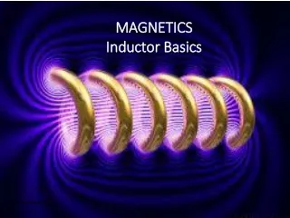
Inductor. Arising from Faraday's law , the inductance L may be defined in terms of the emf generated to oppose a given change in current:. Resistor A.C. Response. Capacitor A.C. Response.

E N D
Inductor Arising from Faraday's law, the inductance L may be defined in terms of the emf generated to oppose a given change in current:
Capacitor A.C. Response • The applied voltage signal is continually changing from a positive cycle to a negative cycle at a rate that is determined by the frequency (a sine wave voltage), so the capacitor is either being charged or discharged on a continuous basis. As the capacitor charges or discharges a current flows through it which itself is restricted by the internal reactance of the capacitor
Inductor A.C. Response • When the current in an Inductor changes, a back emf is created that opposes the change in current, and the faster the initial change in current the greater the back emf. So it is not surprising that, the faster rates of change of current that occur as the frequency of the wave increases, produce a greater back emf effect that in turn, reduces current flow more than it does at lower frequencies.
Impedance While Ohm's Law applies directly to resistors in DC or in AC circuits, the form of the current-voltage relationship in AC circuits in general is modified to the form: where I and V are the rms or "effective" values. The quantity Z is called impedance. For a pure resistor, Z = R. Because the phase affects the impedance and because the contributions of capacitors and inductors differ in phase from resistive components by 90 degrees, a process like vector addition (phasors) is used to develop expressions for impedance.
Impedance, Z • RC circuit RL circuit
Series LCR Circuit • The resonance of a series RLC circuit occurs when the inductive and capacitive reactances are equal in magnitude but cancel each other because they are 180 degrees apart in phase. The sharp minimum in impedance which occurs is useful in tuning applications.
Tuning in • LC circuits have a resonance property like mechanical systems such as a pendulum or a mass on a spring: there is a special frequency that it likes to oscillate at, and therefore responds strongly to. • They can be used to tune in to a specific frequency, for example in the station selector of a radio or television. • In an LC circuit, electric charge oscillates back and forth just like the position of a mass on a spring oscillates.
Impedance Matching As a general rule, the maximum power transfer from an active device like an amplifier to an external device like a speaker occurs when the impedance of the external device matches that of the source. That optimum power is 50% of the total power when the impedance of the amplifier is matched to that of the speaker. Improper impedance matching can lead to excessive power use, distortion, and noise problems.