Download
1 / 55
550 likes | 635 Views
Results from the 'S1-Global' cryomodule tests at KEK (8-cav. and DRFS operation). Shin MICHIZONO (KEK). Outline I. 8-cavity installation (S1 global) Total eight cavities are installed. Rather short time operation (for total 3 months, Mon. to Fri. from 1PM to 7PM.) No beam operation

E N D
Results from the 'S1-Global' cryomodule tests at KEK(8-cav. and DRFS operation) Shin MICHIZONO (KEK) • Outline • I. 8-cavity installation (S1 global) • Total eight cavities are installed. • Rather short time operation (for total 3 months, Mon. to Fri. from 1PM to 7PM.) • No beam operation • With circulators at individual input coupler • Dynamic detuning control with piezo • Vector sum operation • Quench analysis • II. DRFS operation (aiming for ilc) • One klystron drives two cavities. • Total 2 klystrons are used. • No beam operation • Without circulators • Dynamic detuning control with piezo • Slow detuning control with piezo • III. Future plan • Related topics • Performance • Diagnostics • Piezo control(8cav. &DRFS) • Quench phenomena (8cav. &DRFS) • Rf overhead (8 cav. &DRFS) • Circulator-less (DRFS) LOLB-2 (June, 2011)
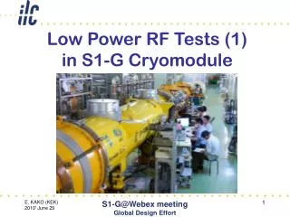
S1 Global LLRF for 8 cav. operation • All the cavities are driven by 5 MW klystron. • Digital LLRF system using an FPGA board on cPCI. • 10 16bit-ADCs are installed. LOLB-2 (June, 2011)
loaded-Q interlock • Calculate the loaded Q from the decay of the rf signal • The interlock works well and contributes to the lower heat load to the cryogenics. RF off Done RF off LOLB-2 (June, 2011)
Real time detuning monitor • The real time detuning monitor is quite helpful to adjust the Piezo tuners. detuned LOLB-2 (June, 2011)
Results from the 'S1-Global' cryomodule tests at KEK(8-cav. and DRFS operation) Shin MICHIZONO (KEK) • Outline • I. 8-cavity installation (S1 global) • Total eight cavities are installed. • Rather short time operation (for total 3 months, Mon. to Fri. from 1PM to 7PM.) • No beam operation • With circulators at individual input coupler • Dynamic detuning control with piezo • Vector sum operation • Quench analysis • II. DRFS operation (aiming for ilc) • One klystron drives two cavities. • Total 2 klystrons are used. • No beam operation • Without circulators • Dynamic detuning control with piezo • Slow detuning control with piezo • III. Future plan • Related topics • Performance • Diagnostics • Piezo control(8cav. &DRFS) • Quench phenomena (8cav. &DRFS) • Rf overhead (8 cav. &DRFS) • Circulator-less (DRFS) LOLB-2 (June, 2011)
Stabilities at 26 MV/m operation By T. Matsumoto • 0.0067%rms(in amplitude),16.5mdeg.rms(in phase) @690~1590us LOLB-2 (June, 2011)
RF stabilities during 2H operation • Vector sum amplitude and phase are kept constant during 2H operation. Gradient Amplitude stability Phase stability LOLB-2 (June, 2011)
Results from the 'S1-Global' cryomodule tests at KEK(8-cav. and DRFS operation) Shin MICHIZONO (KEK) • Outline • I. 8-cavity installation (S1 global) • Total eight cavities are installed. • Rather short time operation (for total 3 months, Mon. to Fri. from 1PM to 7PM.) • No beam operation • With circulators at individual input coupler • Dynamic detuning control with piezo • Vector sum operation • Quench analysis • II. DRFS operation (aiming for ilc) • One klystron drives two cavities. • Total 2 klystrons are used. • No beam operation • Without circulators • Dynamic detuning control with piezo • Slow detuning control with piezo • III. Future plan • Related topics • Performance • Diagnostics • Piezo control(8cav. &DRFS) • Quench phenomena (8cav. &DRFS) • Rf overhead (8 cav. &DRFS) • Circulator-less (DRFS) LOLB-2 (June, 2011)
Dynamic detuning compensation with piezo • Piezo works well to compensate the dynamic detuning LOLB-2 (June, 2011)
Detuning change during 2H operation • DESY: 33Hz, FNAL:12~38Hz, KEK: 5~10Hz FNAL quench DESY KEK KEK KEK KEK • Rather stiff at A-1~4. (~1/4 compared with C-1~4) LOLB-2 (June, 2011)
Ql change during operation • Ql changes are also observed at KEK. • This is still open question. (difficult to explain by only coupler lod) FNAL DESY KEK KEK KEK KEK LOLB-2 (June, 2011)
Results from the 'S1-Global' cryomodule tests at KEK(8-cav. and DRFS operation) Shin MICHIZONO (KEK) • Outline • I. 8-cavity installation (S1 global) • Total eight cavities are installed. • Rather short time operation (for total 3 months, Mon. to Fri. from 1PM to 7PM.) • No beam operation • With circulators at individual input coupler • Dynamic detuning control with piezo • Vector sum operation • Quench analysis • II. DRFS operation (aiming for ilc) • One klystron drives two cavities. • Total 2 klystrons are used. • No beam operation • Without circulators • Dynamic detuning control with piezo • Slow detuning control with piezo • III. Future plan • Related topics • Performance • Diagnostics • Piezo control(8cav. &DRFS) • Quench phenomena (8cav. &DRFS) • Rf overhead (8 cav. &DRFS) • Circulator-less (DRFS) LOLB-2 (June, 2011)
Cavity equation • The cavity should satisfy the differential equation. • In addition directivity (~20dB) of rf monitor-coupler should be concerned. • -> The directivity can be corrected using this formula. LOLB-2 (June, 2011)
Quench phenomena • Loaded Qs are calculated from cavity differential equation. • Only the end of rf pulse shows the quench. • Rather stiff at A-1~4. (~1/4 compared with C-1~4) LOLB-2 (June, 2011)
Quench phenomena (2) • Detuning change at C-4 affects the VS leading to C-1 Quench LOLB-2 (June, 2011)
Results from the 'S1-Global' cryomodule tests at KEK(8-cav. and DRFS operation) Shin MICHIZONO (KEK) • Outline • I. 8-cavity installation (S1 global) • Total eight cavities are installed. • Rather short time operation (for total 3 months, Mon. to Fri. from 1PM to 7PM.) • No beam operation • With circulators at individual input coupler • Dynamic detuning control with piezo • Vector sum operation • Quench analysis • II. DRFS operation (aiming for ilc) • One klystron drives two cavities. • Total 2 klystrons are used. • No beam operation • Without circulators • Dynamic detuning control with piezo • Slow detuning control with piezo • III. Future plan • Related topics • Performance • Diagnostics • Piezo control(8cav. &DRFS) • Quench phenomena (8cav. &DRFS) • Rf overhead (8 cav. &DRFS) • Circulator-less (DRFS) LOLB-2 (June, 2011)
Schematic of the DRFS at S1-global DRFS #1 DRFS #2 MA modulator LOLB-2 (June, 2011)
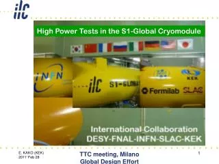
DRFS klystron and WG system with module • Feb.8 : LOLB-2 (June, 2011)
DRFS klystron and WG system • Feb.8 : Phase shifter Phase shifter LOLB-2 (June, 2011)
Some photos Modulator on the ground DRFS #2 DRFS #1 LOLB-2 (June, 2011)
Some photos (2) MA modulator DRFS #1 Phase shifter LOLB-2 (June, 2011)
HLRF and LLRF LLRF rack is located just downstream of cryomodule -> radiation dose will be measured. Magic-T and WG system LOLB-2 (June, 2011)
S1 Global 3rd stage (DRFS)(1) • Digital system is located in the tunnel • Fast interlock (and Arc detectors, VSWR meter) are located on the ground. • cPCIs are used for the monitor and also they are the backup digital system. LOLB-2 (June, 2011)
Field regulation with uTCA • cERL like uTCA FPGA system was installed. • An FPGA board have 4 16-bit ADCs and 4 16-bit DACs. • Two cavity-pickups, klystron output, reflection are observed. • The system was located in the tunnel. LOLB-2 (June, 2011)
RF distribution at DRFS • One klystron drives two cavities. • Circulator-less system. • Same (amplitude and phase) reflection signals go to the dummy load.(blue line) • Un-balanced reflection signals move to the klystron. (red line) • -> careful operation is required to protect the klystron. • Phase-shifters are introduced to evaluate the system. (not to be used at ilc-DRFS) LOLB-2 (June, 2011)
Circulator-less system • Elimination of circulators are proposed at DRFS. • The study to eliminate the circulators were partly carried out at STF-1. However, there was a big circulator between cavities and a klystron. • This is the first time to eliminate all the circulators. With circulators Without circulators Cavity input | Vf | | Vf | Cavity input exists even after RF off Results at STF-1 Normalized by klystron output Vf amplitude ratio (%) Vf amplitude ratio (%) LOLB-2 (June, 2011)
Results from the 'S1-Global' cryomodule tests at KEK(8-cav. and DRFS operation) Shin MICHIZONO (KEK) • Outline • I. 8-cavity installation (S1 global) • Total eight cavities are installed. • Rather short time operation (for total 3 months, Mon. to Fri. from 1PM to 7PM.) • No beam operation • With circulators at individual input coupler • Dynamic detuning control with piezo • Vector sum operation • Quench analysis • II. DRFS operation (aiming for ilc) • One klystron drives two cavities. • Total 2 klystrons are used. • No beam operation • Without circulators • Dynamic detuning control with piezo • Slow detuning control with piezo • III. Future plan • Related topics • Performance • Diagnostics • Piezo control(8cav. &DRFS) • Quench phenomena (8cav. &DRFS) • Rf overhead (8 cav. &DRFS) • Circulator-less (DRFS) LOLB-2 (June, 2011)
Cavity equation • The cavity should satisfy the differential equation. • In addition directivity (~20dB) of rf monitor-coupler should be concerned. • -> The directivity can be corrected using this formula. LOLB-2 (June, 2011)
Diagnostics (Ql evaluation) • The simple Ql estimation from decay curve does not work when the rf input exist after rf switched off. • The calculated Ql values agree well between filling and decay. • Although simple Ql calculation is useful for interlock, this is not sufficient for diagnostics. Ql from decay Cav1 Ql at filling Ql at decay Cav2 LOLB-2 (June, 2011)
Results from the 'S1-Global' cryomodule tests at KEK(8-cav. and DRFS operation) Shin MICHIZONO (KEK) • Outline • I. 8-cavity installation (S1 global) • Total eight cavities are installed. • Rather short time operation (for total 3 months, Mon. to Fri. from 1PM to 7PM.) • No beam operation • With circulators at individual input coupler • Dynamic detuning control with piezo • Vector sum operation • Quench analysis • II. DRFS operation (aiming for ilc) • One klystron drives two cavities. • Total 2 klystrons are used. • No beam operation • Without circulators • Dynamic detuning control with piezo • Slow detuning control with piezo • III. Future plan • Related topics • Performance • Diagnostics • Piezo control(8cav. &DRFS) • Quench phenomena (8cav. &DRFS) • Rf overhead (8 cav. &DRFS) • Circulator-less (DRFS) LOLB-2 (June, 2011)
Typical operation of VS control Pf Pb to kly. • Under the low reflection condition, VSWR is ~1.1. LOLB-2 (June, 2011)
Detuning and Ql under typical operation Red:Ql by decay Cav. C-1 Blue: Ql by cavity eq. Cav. C-2 • Loaded Qs calculated simple time decay are not correct. LOLB-2 (June, 2011)
Un-matched operation with VS control(different detuning) Pf Df1>Df2 Pb to kly. • Reflection to the klystron is ~25kW (max VSWR=3) • Vector sum is still regulated. (0.04%rms, 0.06deg.rms) LOLB-2 (June, 2011)
Un-matched operation (detuning and Ql) Blue: Ql by cavity eq. Cav. C-1 Red:Ql by decay Cav. C-2 • Although Qls by decay show low-value, Qls based on cavity equation show reasonable values. LOLB-2 (June, 2011)
Un-matched operation with VS control(different waveguide-length) Pf Df1~Df2 Pb to kly. • Reflection to the klystron is ~20kW (max VSWR=2.8) • Vector sum is still regulated. (0.015%rms,0.07deg.rms) LOLB-2 (June, 2011)
Un-matched operation (detuning and Ql) Cav. C-1 Cav. C-2 • Ql by decay: ~4e6 • Ql by cavity equation: ~2.5e6 LOLB-2 (June, 2011)
Results from the 'S1-Global' cryomodule tests at KEK(8-cav. and DRFS operation) Shin MICHIZONO (KEK) • Outline • I. 8-cavity installation (S1 global) • Total eight cavities are installed. • Rather short time operation (for total 3 months, Mon. to Fri. from 1PM to 7PM.) • No beam operation • With circulators at individual input coupler • Dynamic detuning control with piezo • Vector sum operation • Quench analysis • II. DRFS operation (aiming for ilc) • One klystron drives two cavities. • Total 2 klystrons are used. • No beam operation • Without circulators • Dynamic detuning control with piezo • Slow detuning control with piezo • III. Future plan • Related topics • Performance • Diagnostics • Piezo control(8cav. &DRFS) • Quench phenomena (8cav. &DRFS) • Rf overhead (8 cav. &DRFS) • Circulator-less (DRFS) LOLB-2 (June, 2011)
Adaptive detuning correction via EPICS • DC piezo bias is controlled every ~2 min. for detuning correction. • The detuning after filling were kept constant Detuning correction • Even these simple (and slow) detuning correction looks promising to compensate the long-time detuning fluctuation (microphonics). Piezo output to change from 0Hz to -50Hz LOLB-2 (June, 2011)
RF waveform and detuning LOLB-2 (June, 2011)
Results from the 'S1-Global' cryomodule tests at KEK(8-cav. and DRFS operation) Shin MICHIZONO (KEK) • Outline • I. 8-cavity installation (S1 global) • Total eight cavities are installed. • Rather short time operation (for total 3 months, Mon. to Fri. from 1PM to 7PM.) • No beam operation • With circulators at individual input coupler • Dynamic detuning control with piezo • Vector sum operation • Quench analysis • II. DRFS operation (aiming for ilc) • One klystron drives two cavities. • Total 2 klystrons are used. • No beam operation • Without circulators • Dynamic detuning control with piezo • Slow detuning control with piezo • III. Future plan • Related topics • Performance • Diagnostics • Piezo control(8cav. &DRFS) • Quench phenomena (8cav. &DRFS) • Rf overhead (8 cav. &DRFS) • Circulator-less (DRFS) LOLB-2 (June, 2011)
RF overhead @flat-top 10% overhead necessary. Average power 11% If we allow 50Hz detuning, 7% overhead is required . 4% Variation inside pulse Minimum 3% rf overhead is necessary. LOLB-2 (June, 2011)
Long term stability (microphonics) A-2 No piezo control Adaptive control No piezo control A-3 • Microphonics are about 3~5Hz rms. • Since KEK cavities are stiff enough, the effect of adaptive piezo control is not clear. LOLB-2 (June, 2011)
Results from the 'S1-Global' cryomodule tests at KEK(8-cav. and DRFS operation) Shin MICHIZONO (KEK) • Outline • I. 8-cavity installation (S1 global) • Total eight cavities are installed. • Rather short time operation (for total 3 months, Mon. to Fri. from 1PM to 7PM.) • No beam operation • With circulators at individual input coupler • Dynamic detuning control with piezo • Vector sum operation • Quench analysis • II. DRFS operation (aiming for ilc) • One klystron drives two cavities. • Total 2 klystrons are used. • No beam operation • Without circulators • Dynamic detuning control with piezo • Slow detuning control with piezo • III. Future plan • Related topics • Performance • Diagnostics • Piezo control(8cav. &DRFS) • Quench phenomena (8cav. &DRFS) • Rf overhead (8 cav. &DRFS) • Circulator-less (DRFS) LOLB-2 (June, 2011)