Download
1 / 19
190 likes | 567 Views
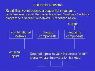
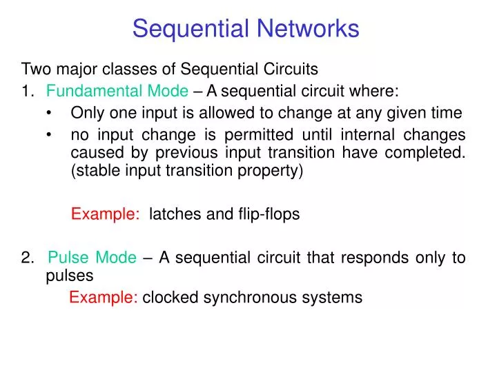
Sequential Networks. Two major classes of Sequential Circuits Fundamental Mode – A sequential circuit where: Only one input is allowed to change at any given time

E N D
Sequential Networks • Two major classes of Sequential Circuits • Fundamental Mode – A sequential circuit where: • Only one input is allowed to change at any given time • no input change is permitted until internal changes caused by previous input transition have completed. (stable input transition property) • Example: latches and flip-flops • 2. Pulse Mode – A sequential circuit that responds only to pulses • Example: clocked synchronous systems
Model of Sequential Networks Output Variable, Z Input Variables, X m xi (t) n Combinational Logic Circuit yi (t) s-bit Next State Excitation Variables Ei (X,Y) s-bit Present State Variables, Y yi (t+ti) Memory Elements - flip-flop - latch - register - PROM s s
Sequential Logic Model • Composed of Combinational Logic and Memory Elements • Behavior is Given by Logic values at Discrete Time Instances • Discrete Time Instances are Given by Clock Signal • Memory Elements • Edge-Triggered Flip-Flops • Level-Sensitive Latches • Memory Elements Can Only Load at Discrete Time Instance
Signal Signal Review voltage time Pw rising edge falling edge - clock period (in Seconds) Pw - pulse width (in Seconds) f– clock frequency (in Hertz) f = 1/ duty cycle = Pw / duty cycle- ratio of pulse width to period (in %)
Clock Signal Example What is the pulse-width of a 4.77 MHz clock with a 30% duty cycle? = 1/f = (4.77×10⁶)-1 = 2.096 ×10-7 = 210 ns Pw = (duty cycle) × = (0.3) × (210 ns) = 63 ns What about clock rise- and fall-time? Clocks are normally defined as having maximum rise and fall times (e.g., time between 10% and 90% values) or they are implied through pulse width specifications.
S Q J Q D Q T Q R K Q Q Q Q Common Memory Element - Flip-Flops Most Commonly Encountered Device is the D-flip-flop Behavior is Described by Characteristic Table or Equation
Concept of State • The Q Outputs of the Flip-Flops Form a State Vector • A Particular Set of Outputs is the Present State • The Particular State Vector that will Occur at the Next Discrete Time is the Next State • A Sequential Circuit described in Terms of State is a Finite State Machine (FSM)
FSM Analysis Example x A B CLK y State Equations: Preset State: A (t)B (t) Next State: A(t+1)B(t+1)
Representing/Describing FSMs Transition Table Note a State Table does not necessarily have the state assignment 0/0 State Diagram 1/0 00 10 0/1 Present State 0/1 0/1 1/0 Input 1/0 Output 1/0 01 11
Representing/Describing FSMs State Table Timing Diagram CLK A Note: propagation delays and change in y before clock edge B x y
FSM Design • Specification Given as One of Previous Descriptions • State Table • State Equations • State Diagram (Easiest to Generate Initially) • ASM Chart (Preferred) • Designer’s Job is to Generate Schematic • Instead of Characteristics, we are Given Excitations • Individual flip-flops have Specific Excitations
S Q J Q D Q T Q R K Q Q Q Q Flip-Flop Excitations Most Commonly Encountered Device is the D-flip-flop Input Behavior is Described by Excitation Table or Equation
Alternate Scheme for Mapping Excitation for SR Latch in One Map • S, R, s, and r cannot be 1 at the same time, one map can be used for generating Set and Reset equations • For Set must encircle S and s is don’t care • For Reset must encircle R and r is don’t care
Vending Machine Example(US version) • Soft drink sells for $.75 • Machine accepts quarter and half-dollar coins • Input x1 =1 if machine receives a half-dollar • Input x2 = 1 if machine receives a quarter • Output z1 = 1 if machine is to give drink • Output z2 = 1 if machine is to give change
Vending Machine ExampleState Diagram and State Table Q1, machine received a quarter Q0, initial state without money Q2, machine received a half-dollar
Vending Machine ExampleState Assignment and Transition Table
Vending Machine ExampleSR Implementation with Single Maps y1 y2 x1 x2 x1 x2 y1 y2 0 0 0 1 1 1 1 0 y1 y2 0 0 0 1 1 1 1 0 0 0 0 0 r r d S r S d r r r S d R s R d 0 1 0 1 1 1 1 1 d d d d d d d d s R d R r r d r 1 0 1 0
Vending Machine ExampleOutputs z1 z2 x1 x2 x1 x2 y1 y2 0 0 0 1 1 1 1 0 y1 y2 0 0 0 1 1 1 1 0 0 0 0 0 d d 1 d d 0 1 0 1 1 1 1 1 d d d d d d d d 1 d 1 d 1 1 0 1 0