Download
1 / 20
210 likes | 563 Views
Unit 1 GD&T. Instructor: James Thornburgh. Agenda: Inspection & Gauging 5 Steps to GD&T GD&T in AutoCAD STP. Inspection & Gauging. Functional Gauging Using Fixtures to check a part Go/ No-Go Gauges Open Gauging Using Measurements to inspect Tells you what is Wrong Feature of Size

E N D
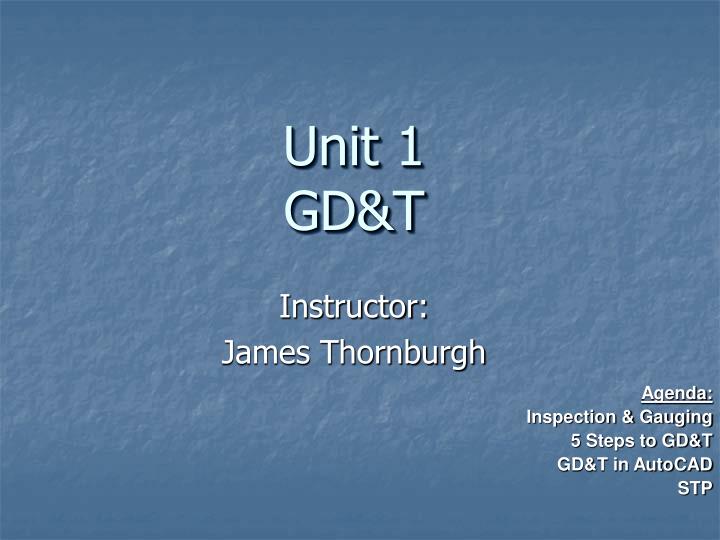
Unit 1GD&T Instructor: James Thornburgh Agenda: Inspection & Gauging 5 Steps to GD&T GD&T in AutoCAD STP
Inspection & Gauging • Functional Gauging • Using Fixtures to check a part • Go/ No-Go Gauges • Open Gauging • Using Measurements to inspect • Tells you what is Wrong • Feature of Size • Things that can be directly measured
11.200 ± .002 10.000 15.500
11.200 ± .002 .001 M A B C B A C 10.000 Note: Datum A forms the bottom surface of the hole, and so the tolerance zone is a perfect, right cylinder – resting on Datum A and located from Datum B and Datum C. 15.500
11.200 ± .002 .001 M A B C B A C 10.000 It tells us thesizeandshapeof the tolerance zone for the hole center 15.500
11.200 ± .002 .001 M A B C B A C 10.000 In this case, when the hole is at its’ smallest permissible size, the feature location is in its’ most critical state. 15.500
11.200 ± .002 .001 M A B C B C A In this case, when the hole is at its’ smallest permissible size and perfectly located, the feature is in its’ most critical state, and just fits about the red gage pin.
11.200 ± .002 .001 M A B C M C 10.000 B 15.500
5 Steps • Isolate & define function • Prioritize the Functions • Identify Datum Reference Frame • Select proper Control • Calculate Tolerance Values
GD&T in AutoCAD • Menu • Dimension • Tolerance • Keyboard • tol
GD&T Dialog Box Diameter Material Condition
STP • Statistical Process Control • Process for checking the quality of parts • Keeps track of trends in production
ANSI Limits and Fits • Running & Sliding • Allow clearance space for lubrication • RC • Locational • Between mating parts • LC, LT, LN • Force • Tight fits • FN Appendixes 7-11
Lab Assignments • Lab • Prob 16.2-16.4