Download
1 / 18
180 likes | 181 Views
This review discusses the requirements, challenges, and strategies for aligning and assembling a cryomodule, including dealing with differential thermal contractions and position changes between components. It also outlines the steps involved in the assembling process.

E N D
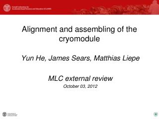
Alignment and assembling of the cryomodule Yun He, James Sears, Matthias Liepe MLC external review October 03, 2012
Outline • Requirements and challenges • Differential thermal contractions • Material properties • Axial differential thermal contractions among components at cold • Beamline vertical thermal contraction at cold • Dealing with differential thermal contractions • Position change between vacuum vessel and coldmass • Position change between HGRP and beamline • Position change between 40K shield and coldmass • Assembling steps Yun HE, MLC External Review
Requirements and challenges • Requirements • Allowable transverse offset (x,y): 2mm for cavities, 1.6 mm for quads • Allowable pitch: 1.5 mrad (1.2 mm over the length of cavity) • Alignment is performed at room temperature • Tolerances maintained throughout thermal cycling, vacuum pumping and transport • Challenges • Different material coefficients of thermal expansion among interfacing components Yun HE, MLC External Review
Differential thermal contractions • Temperature dependent material properties • Axial differential thermal contractions among components at cold • Beamline vertical thermal contraction at cold Yun HE, MLC External Review
Material properties -- coefficient of thermal expansion Used material data from NIST for calculations Data from NIST Most of these values are higher than TTF used Table from Norihito. Ohuchi’s talk, SRF2009 Table from Carlo Pagani’s paper, SRF2005
Axial differential thermal contractions among components at cold Axial displacement due to thermal contractions of materials at cold Sliding post Fixed point Sliding post 9.8 m, vacuum vessel at room temperature 7.5 mm -- HGRP 9.5 mm -- HGRP 0.8 m 15.5 mm – thermal shield 19 mm – thermal shield 8 mm – beamline 6.5 mm – beamline 1 mm thermal contraction – cavity LHe vessel Yun HE, MLC External Review
Vertical beamline displacement at cold 40K 140 mm 5K 500 mm Moved up by ~1.2 mm Yun HE, MLC External Review
Dealing with differential thermal contractions • Position change between vacuum vessel and coldmass • Position change between HGRP and beamline • Position change between 40K shield and coldmass Yun HE, MLC External Review
Dealing with position change between vacuum vessel and coldmass • Longitudinal: middle post is fixed, while the side posts are slid able • Vertical: Bellows section allows displacements of beamline at cold • Beamline port on end flange of warm-cold transition will be higher • by 1.2 mm, so the bellows will be bent at room temperature • Coupler design allows a transverse offset up to10 mm • Couplers will be offset at room temperature thus will be straight at cold • Brass bushing allows side post to slide on vacuum vessel top flange • Replace it with roller bearings? Yun HE, MLC External Review
Dealing with position change between HGRP and beamline • Cavity flexible support • Allows 1 mm displacement • A bellows section in chimney of cavity • Key alignment of component supports • Allows beamline components to slide longitudinally relative to HGRP • Bellows in HOM absorbers • HOM loads are made of stainless steal but the bellows in the HOM loads will take the difference between the length changes of the cavities and HOM loads and the HGRP • Alignment results from Injector Cryomodule WPM measurements • Cavity string was aligned to 0.2 mm after cool-down Yun HE, MLC External Review
Dealing with position change between shield and cold mass (posts) Sliding post Fixed post Sliding post Left/right posts can move relative to shield in axial direction during cool-down • Atroom temperature, side post is • offset to vac vessel port center • Concentric to shield opening • At cold, side post is moved due to HGRP contraction, became • concentric to vac vessel port center • Slightly offset to shield opening center Yun HE, MLC External Review
Assembling steps Yun HE, MLC External Review
Assembling steps -- assemble beamline , weld 2K-2 phase line • Assemble beamline in the clean room on rail support; • Leak check and keep beamline in UHV • Level components in horizontal direction (Roll) with sine-plate within 0.0005”/10”; • No need to align them in other directions as bellows in HOM absorbers allow for adjustment once the beamline string is mounted to precision machined HGRP supports • Weld 2K-2 phase pipe to chimneys of cavity/magnets LHe vessels; Yun HE, MLC External Review
Assembling steps -- assemble beamline , mount to HGRP/posts • Mount beamline string onto HGRP which is supported by three posts on assembly frame; • Install tuners Weld chimney between HGRP and 2K-2 phase pipe Connect supports Yun HE, MLC External Review
Assembling steps – insert cooling lines, instrumentation wires,40K shield • Install 2K, 5K cooling pipes; • Install 40K shield upper sheets and 40K cooling pipes; • Connect jumpers to 5K, 40K intercepts; • Instrumentation wires • Install 40K shield lower sheets; • Magnetic shields; • MLI Yun HE, MLC External Review
Assembling steps – insert cold mass into vacuum vessel • Rail cold mass into vacuum vessel; • Mount alignment brackets to support post; • Jack up brackets to relieve the cold mass weight from rails; • Align post position with respect to the vacuum vessel fiducial points Rails for cold mass insertion Alignment bracket Vacuum vessel reference arm, with precision machined conical centering surface for a TH-sphere or reflector Yun HE, MLC External Review
Assembling steps – align cold mass to vacuum vessel references • Adjust positions of posts relative to vacuum vessel reference arms; • Lock the position of middle post and the position of side posts in horizontal direction; • Install cryogenic valves; • connections of valves to pipes Position of posts can be adjusted via rods/screws Reference surfaces for TH spheres Support bracket Support post Yun HE, MLC External Review
The End Yun HE, MLC External Review