Download
1 / 20
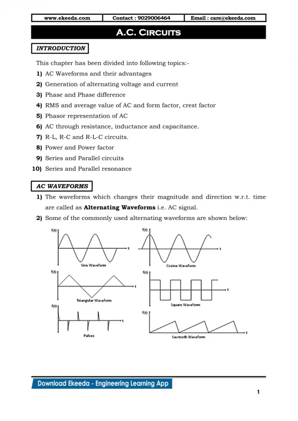
210 likes | 345 Views
Unit 17 Inductance in AC Circuits. Unit 17 Inductance in AC Circuits. Objectives: Discuss the properties of inductance in an alternating current circuit. Discuss inductive reactance. Compute values of inductive reactance and inductance.

E N D
Unit 17 Inductance in AC Circuits Objectives: Discuss the properties of inductance in an alternating current circuit. Discuss inductive reactance. Compute values of inductive reactance and inductance. Discuss the relationship of voltage and current in a pure inductive circuit.
Unit 17 Inductance in AC Circuits Objectives: Be able to compute values for inductors connected in series or parallel. Discuss reactive power (VARs).
A continually changing magnetic field induces a voltage into any conductor. Unit 17 Inductance in AC Circuits
Unit 17 Inductance in AC Circuits As current flow increases through a coil, a magnetic field is created around the coil.
Unit 17 Inductance in AC Circuits As current flow decreases through a coil, the magnetic field collapses.
Unit 17 Inductance in AC Circuits The applied voltage and induced voltage are 180° out of phase.
Unit 17 Inductance in AC Circuits Inductive reactance is the current-limiting property of an inductor. The inductive reactance symbol is XL. The unit of measurement is in ohms, just like resistance, and Ohm’s law formulas can be used.
Unit 17 Inductance in AC Circuits Inductive Reactance XL = 2πfL XL = inductive reactance 2 = a constant π = 3.1416 F = frequency in hertz (Hz) L = inductance in henrys (H)
Unit 17 Inductance in AC Circuits Coils with turns closetogether produce more inductance than coils with turns farapart.
Unit 17 Inductance in AC Circuits Three factors that determine induced voltage: 1. The number of turns of wire. 2. The strength of the magnetic field. 3. The speed of the cutting action.
Unit 17 Inductance in AC Circuits Circuit current is limited by inductive reactance. XL = 2πfL = 377 x .8 = 301.6 Ω I = E / XL = 120 V / 301.594 Ω = 0.398 A
Unit 17 Inductance in AC Circuits Inductors connected in series. LT = L1 + L2 + L3 XLT = XL1 + XL2 + XL3
Unit 17 Inductance in AC Circuits Inductors connected in parallel. 1/LT = 1/L1 + 1/L2 + 1/L3 1/XLT = 1/XL1 + 1/XL2 + 1/XL3
Unit 17 Inductance in AC Circuits In a pure inductive circuit, the current lags the applied voltage by 90°. Applied Voltage Current Flow
Unit 17 Inductance in AC Circuits Reactive Power VARs = EL x IL VARs = EL2 / XL VARs = IL2 x XL EL = voltage applied to an inductor IL = current flow through an inductor XL = inductive reactance
Unit 17 Inductance in AC Circuits Review: Induced voltage is proportional to the rate of change of current. Induced voltage is always opposite in polarity to the applied voltage. Inductive reactance is a countervoltage that limits the flow of current, as does resistance.
Unit 17 Inductance in AC Circuits Review: Inductive reactance is measured in ohms. Inductive reactance is proportional to the inductance of the coil and the frequency of the line. Inductive reactance is symbolized by XL. Inductance is measured in henrys (H) and is symbolized by the letter L.
Unit 17 Inductance in AC Circuits Review: When inductors are connected in series, the total inductance is equal to the sum of all the inductors. When inductors are connected in parallel, the reciprocal of the total inductance is equal to the sum of the reciprocals of all the inductors.
Unit 17 Inductance in AC Circuits Review: The current lags the applied voltage by 90° in a pure inductive circuit. Reactive power is measured in VARs.