Download
1 / 29
290 likes | 425 Views
QDIS CO., LTD. For your best convenience. LR MODULE SPECIFICATION (Discover4, RangeRover 2010model). -. MODEL: QVL-RCD-D4-MAIN-V1 -. P/N : RD-1001-001. -D4 Interface Feature. Improved display quality Working on NTSC, PAL External Touch screen available by NAVI-SEL

E N D
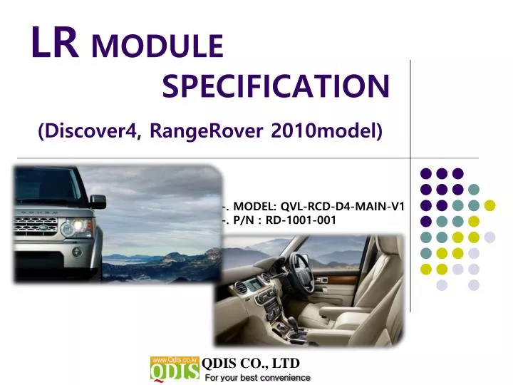
QDIS CO., LTD For your best convenience LR MODULE SPECIFICATION(Discover4, RangeRover 2010model) -. MODEL: QVL-RCD-D4-MAIN-V1 -. P/N : RD-1001-001
-D4 Interface Feature • Improved display quality • Working on NTSC, PAL • External Touch screen available by NAVI-SEL • AV1-SEL, REAR-SEL are added (For Rear-CAM Power) • Rear CAM detection by CAN • Possible to adjust displayed RGB, AV sources in Factory Mode • Possible to display OSD with no connection of AV sources -2-
-Precaution - You must keep the car key taken off from the car while you workthis and finally, connect power of the interface. - When to connect the interface cable, you must keep the power cable taken off. - You must work this at the environment without any static electricity or damages. - All of process on this installation should be done by professionals. - You must not break the labels attached on the board, if it’s broken, no warranty. - When you receive this package you have to check whether there’s any parts not included and you have to contact us right away. - Our repair service do not accept any problems caused by user’s any fault or carelessness. -3-
-Main Spec. 1. Input Spec. (MULTI VIDEO INTERFACE) -. 3 x A/V Input (External video source). -. 1 x CVBS(REAR CAMERA) Input. (Rear camera source) -. 1 x Analog RGB Input (Navigation System output) -. 1 x LCD Input (Car system Input) -. 1 x GVIF Input 2. Output Spec. -. 1 x GVIF Output -. 4 x Audio Select (12V power comes out from 4wires of cable by video, Navi mode) -. 3 X 12V SEL 3. Power Spec. - Input Power : 8VDC ~ 18VDC - Consumption Power : 12WATT, Max 4. Switch Input mode - Input Video MUTE Function : Possible to make each input mute by operating Dip S/W. - Possible to switch Input mode with switch for source toggle - Possible to switch mode through CAN -4-
-System Composition IR Switch for source toggle OEM Navi Button (Can Intrface) MCU NAVIGATION Input (Analog RGB) VIDEO MUX DISPLAY Car Installation OEM LCD A/V 1 VIDEO CIRCUIT A/V 2 A/V OUT HEADREST MONITOR A/V 3 CVBS (Rear camera) POWERCIRCUIT (CAR MAIN BOARD) Car Screen Input SEL-OUT Power Input (+8VDC ~ +18VDC) Dip S/W -5-
-Outline Dimension 155mm * 91mm * 20mm 125mm 103mm 21mm -6-
-External Appearance LCD-OUT DIP S/W IR LED MODE POWER SEL A/V(IN/OUT) RGB(IN) -7-
*RGB-IN Connect ① ② ⑦ ③ ④ ⑤ ⑥ ① R DATA (Red) ② G DATA (Green) ③ B DATA (Blue)④ SYNC (White) ⑤ GND (Black) ⑥ N.C ⑦ N.C -Connector Pin Assignment *Power Connect ① ③ ④ ⑤ ⑥ ② ⑦ ① ACC (Red) ② GND (Black) ③ CAN-H (Green+Brown) ④ CAN-L (Green) ⑤ F-CAM-DET (Orange) ⑥ SAFE (Violet) ⑦ REAR-C (Grey) -8-
-Connector Pin Assignment * Power Cable FILTER & FUSE BOX ACC : 8v~18V GND CAN(H) CAN(L) F-CAM-DET SAFE REAR-C 1m
-DIP SW ※ ON : DOWN, OFF : UP ※DIP S/W Use Example -. Use Input Mode : MAIN + A/V 3 -. Rear Camera : When to be installed \ on CVBS 4 ▷ DIP S/W : 1,2,3 - ON (INPUT MODE SKIP) ▷ DIP S/W : 4 - OFF (enable A/V3) ▷ DIP S/W : 5 - OFF ▷ DIP S/W : 6 - OFF ▷ DIP S/W : 7 - ON (enable CVBS4) ▷ DIP S/W : 8 - OFF -10-
-How to use Remote Dimension: 85 * 40 * 8 (mm) POWER MENU : OSD Menu OK : Select ▲ : Up ▼ : Down ◀ : Left (Factory Menu : Long press for 5 sec) ▶ : Right *FACTORYMODE (Interface setting) : Operated with pressing ▲ -> ▼ -> ▲ ->MENU keys in the remote in sequence. -11-
-OEM Button ※ Should connect CAN wire before using the original button • Descover4 • Range Rover NAV Button(under an original monitor) AV Switching by Navi button on Radio (CAN Wiring needed) MODE Button(on the steering wheel) Press more than 2sec : MODE Change Press: Switch to Main screen -12-
-OEM Button ※AV Switching by Navi button on Radio (CAN Wiring needed) ※ CAN Wiring! Connect the twisted yellow and yellow+green wires which are behind of LCD to provided CAN wires from Interface set. CAN High – Yellow+Green wire CAN Low – Yellow wire -13-
-OSD(On Screen Display) · Analog RGB Mode · Video Mode • IMAGE Menu • BRIGHTNESS • CONTRAST • SATURATION • HUE • SHARPNESS • USER IMAGE -14-
OSD(On Screen Display) · Analog RGB Mode · Video Mode • OSD Menu • LANGUAGE • OSD TRANS • OSD H_POS • OSD V_POS -15-
OSD(On Screen Display) · Analog RGB Mode · Video Mode • UTIL Menu • FACTORY RESET : Initializing (Each RGB, AV Initializing) -16-
OSD(On Screen Display) · FactoryMode -Activated by pressing ◀ button of remote or ▲ → ▼ → ▲ →MENU in order. • Factory Mode • IMAGE : - H-POSITION : Move to Left, Right • - V-POSITION : Move to Up, Down • PARK : Refer to “parking guide line” page. -17-
OSD(On Screen Display) · FactoryMode -Activated by pressing ◀ button of remote or ▲ → ▼ → ▲ →MENU in order. • Factory Mode • UTIL : - REAR CAM Detection SELECT : – LAMP : By rear lamp, CAN – By CAN • - NAVI MODEL : KD680_NEW – Chinese Navi (upgraded version) • NAV N GO (I-Go), ITURAN – Europe and middle east • DEFAULT • - FACTORY RESET : Initializing -18-
-How to use Parking Guide Line ① ① Set “PARK ENABLE” to “ON” on The park mode like the left picture no.1 * If you would like to remove this line, just select “ON” on the above process. ② ② After setting, once you put the gear to rear, the screen displays the parking guide line like the left picture no. 2. -19-
How to use parking guide line ③ ③ The way to move the lines: Once you operate “*Factory Mode” again, when the lines are appeared,OSD image will be displayed like the left picture no.3After that, you select “PARK” and can move the lines by ‘UP’,’DOWN’ keys of keypad. H-POSITION: Move to Left, Right V-POSITION: Move to Up, Down * FACTORY Mode : This all processes should be operated on ‘Factory Mode’ and ‘Factory Mode’ is operated with pressing UP->DOWN->UP->MENU keys of the keypad sequently. -20-
-Product Composition (Discovery4) Remote: 1 EA Power Cable: 1 EALVDS Cable: 1 EA A/V Cable: 1 EANavi Cable: 1 EAGround Cable: 1 EAToggle S/W: 1 EA Sub-Board : 1 EATouch Board : 1EA SEL (12V) Cable: 1 EATouch Cable : 1 EA FPC Cable : 1 EA -21-
-Installation Sturcture (Discovery4) CAN GREEN+YELLOW GREEN Sub-B/D OEM Touch LED DIP S/W Remote MODE LCD-OUT Ground Cable Provided FPC D4 VIDEO INTERFACE LCD OEM FPC SEL(12V) POWER A/V(IN/OUT) RGB(IN) Touch B/D NAVI-SEL AV1-SEL REAR-SEL ACC GND AV1 AV2 AV3 CAN(H) REAR C R G B GND SYNC AV/OUT CAN(L) F-CAM-DET AUDIO R SAFE AUDIO L 노랑 노랑 빨강 흰색 REAR-C VIDEO -22-
-Installation Instruction (Discovery4) ① ② 1. Take apart the indicated OEM touch cable and FPC cable from LCD (For easier installation, disconnect the FPC(①) for a while) 2. Connect the provided FPC cable to the indicated OEM connector. ① ② 3. As the above picture, connect the OEM touch cable (①) to a provided sub-board and the provided FPC cable and sub-board(②). Also connect OEM FPC cable to the provided FPC cable (③)
-Installation Instruction (Discovery4) Touch B/D 5. Connect the sub-board to Interface B/D with LVDS cable 4. Connect sub-board to touch B/D with a ground Cable. 6. Connect the twisted yellow and yellow+green wires which are behind of LCD to provided CAN wires from Interface set. CAN High – Yellow+Green wire CAN Low – Yellow wire
-Product Composition(Range Rover) Remote: 1 EA Power Cable: 1 EALVDS Cable: 1 EA A/V Cable: 1 EANavi Cable: 1 EAGround Cable: 1 EAToggle S/W: 1 EA Sub-Board : 1 EATouch Board : 1EA SEL (12V) Cable: 1 EATouch Cable : 1 EA FPC Cable : 1 EA BY-PASS Cable : 1 EA -25-
-Installation Instruction(Range Rover) ※ The power of interface should be connected with an power of an original monitor CAN GREEN+YELLOW GREEN OriginalFPC LED DIP S/W Remote MODE LCD-OUT LAND ROVER VIDEO INTERFACE OfferedFPC Monitor POWER A/V(IN/OUT) RGB(IN) SEL(12V) NAVI-SEL AV1-SEL Sub-board REAR-SEL ACC GND Original touch AV1 AV2 AV3 CAN(H) REAR C R G B GND SYNC AV/OUT CAN(L) Touch board F-CAM-DET AUDIO R SAFE AUDIO L 노랑 노랑 빨강 흰색 REAR-C VIDEO
- Installation Instruction (Range Rover) 1. Take apart the indicated OEM touch cable and FPC cable from LCD (For easier installation, disconnect the FPC② for a while) originalFPC providedFPC ① ③ ② 2. Connect the provided FPC cable to the indicated OEM connector. OriginalFPC • After taking apart an original touch cable, Connect provided cable to headunit as picture in the left Provided cable Provided cable
- Installation Instruction (Range Rover) 5. Connect the twisted yellow and yellow+green wires which are behind of LCD to provided CAN wires from Interface set. CAN High – Yellow+Green wire CAN Low – Yellow wire • Connect the Sub-board and Touch board ProvidedFPC CAN High CAN Low LVDS Cable Touch cable 6. Connect the twisted yellow and yellow+green wires which are behind of LCD to provided CAN wires from Interface set. CAN High – Yellow+Green wire CAN Low – Yellow wire 터치보드 Original Touch out cable
FAQ 1. When can not change mode. -. Check if the IR Cable (remote control) is connected or not. -. Check if LED is turned on or not. If it is not turned on, Check if power cable is connected or not. -. Check if CAN is connected well. 2. When the screen is displaying only black color. -. Check if 2nd LED is turned on or not. If it is not turned on, please check all video sources that you will connect with the interface is operating well or not. -. Check if interface is connected well. 3. When displayed color of screen is not proper. (If it’s too dark or the color is not proper) -. Try to push “Reset button” on the remote control. If the color of screen keeps on displaying wrong color, you have to ask manufacturer for the problem. -. Try to adjust Color, Contrast, Brightness by the remote. 4. When Back-up camera is not displayed on the screen. -. Turn Dip S/W no.7 on. 5. When the mode you set is not skip. -. Check if Dip S/W is set in proper way. 6. When Main screen on the car is not displayed. -. Check if In/Out cables are connected well. If it keeps showing the same problem, you have to ask manufacturer for the problem. 7. When the screen is displaying only white color. -. Check if out cable is connected well. If it keeps showing the same problem, you have to ask manufacturer for the problem. -29-