Download
1 / 58
580 likes | 756 Views
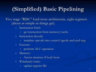
(Simplified) Basic Pipelining. Five stage “RISC” load-store architecture, eight registers (about as simple as things get) Instruction fetch: get instruction from memory/cache Instruction decode: translate opcode into control signals and read regs Execute: perform ALU operation Memory:

E N D
(Simplified) Basic Pipelining Five stage “RISC” load-store architecture, eight registers(about as simple as things get) • Instruction fetch: • get instruction from memory/cache • Instruction decode: • translate opcode into control signals and read regs • Execute: • perform ALU operation • Memory: • Access memory if load/store • Writeback/retire: • update register file
Making Faster Processors • Make the compiler team unhappy • More aggressive optimization over entire program • More resource constraints; caches; HW schedulers • Higher expectations: increase IPC • Make hardware design team unhappy • Tighter design constraints (clock) • Execute optimized code with more complex execution characteristics • Make all stages bottlenecks (Amdahl’s law)
LC314 Computer • Similar to MIPS • Smaller instructions • Slightly different format • Concepts from building pipeline for this simplified ISA apply to MIPS (Project 4)
The Plan • Review basics • Today: focus on optimizations • Next: the memory hierarchy
LC314 Processor • Instruction Set Design (MIPS-like, but simpler) • Makes pipeline explanation easier • Principles extend to MIPS • Only seven instructions! opcode regA regB destReg
Simplified Memory Addressing • Define access size to be 24 bits/3 bytes • Address 0 is at 0th word, or byte 0 • Address 1 is at 1st word, or byte 3 • Address 2 is at 2nd word, or byte 6 • Different from MIPS, but simplifies pictures • Just remember that “+1 word” == “+3 bytes”
LC314 Processor R-type instructions opcode regA regB destReg 23–21 20–18 17–15 14–3 2–0 add: destReg regA + regB nand: destReg regA & regB
LC314 Processor I-type instructions opcode regA regB offsetField 23–21 20–18 17–15 14–0 lw: regB Memory[regA + offsetField] sw: Memory[regA +offsetField] regB beq: if (regA= = regB) PC PC + 1 + offsetField
LC314 Processor O-type instructions opcode unused 23–21 20–0 noop: do nothing halt: halt the simulation
Pipelined Implementation • Break the execution of the instruction into cycles (five, in this case) • Design a separate datapath stage for the execution performed during each cycle • Build pipeline registers (latches) to communicate between the stages
Sample Code (Simple) • Assume eight-register machine • Run the following code on a pipelined datapath add 1 2 3 ; reg 3 = reg 1 + reg 2 nand 4 5 6 ; reg 6 = ~(reg 4 & reg 5) lw 2 4 20 ; reg 4 = Mem[reg2+20] add 2 5 5 ; reg 5 = reg 2 + reg 5 sw 3 7 10 ; Mem[reg3+10] = reg 7
+ + A L U M U X 1 target PC+1 PC+1 0 R0 eq? R1 regA ALU result R2 Register file regB valA M U X PC Inst mem Data mem instruction R3 ALU result mdata R4 valB R5 R6 M U X data R7 offset dest valB Bits 0-2 dest dest dest Bits 15-17 M U X Bits 21-23 op op op IF/ ID ID/ EX EX/ Mem Mem/ WB
+ + A L U M U X 1 0 0 0 0 R0 0 36 R1 0 9 R2 Register file 0 M U X PC Inst mem Data mem nop 12 R3 0 0 18 R4 7 0 R5 41 R6 M U X data 22 R7 0 dest 0 Initial State Bits 0-2 0 0 0 Bits 15-17 M U X Bits 21-23 nop nop nop IF/ ID ID/ EX EX/ Mem Mem/ WB
+ + A L U add 1 2 3 M U X 1 0 1 0 0 R0 0 36 R1 0 9 R2 Register file 0 M U X PC Inst mem Data mem add 1 2 3 12 R3 0 0 18 R4 7 0 R5 41 R6 M U X data 22 R7 0 dest 0 Fetch: add 1 2 3 Bits 0-2 0 0 0 Bits 15-17 M U X Bits 21-23 nop nop nop IF/ ID ID/ EX EX/ Mem Mem/ WB Time: 1
+ + A L U nand 4 5 6 add 1 2 3 M U X 1 0 2 1 0 R0 0 36 R1 1 0 9 R2 Register file 2 36 M U X PC Inst mem Data mem nand 4 5 6 12 R3 0 0 18 R4 7 9 R5 41 R6 M U X data 22 R7 3 dest 0 Fetch: nand 4 5 6 Bits 0-2 3 0 0 Bits 15-17 M U X Bits 21-23 add nop nop IF/ ID ID/ EX EX/ Mem Mem/ WB Time: 2
+ + A L U lw 2 4 20 nand 4 5 6 add 1 2 3 M U X 3 1 4 1 3 2 0 R0 0 36 R1 4 0 36 9 R2 Register file 5 18 M U X PC Inst mem Data mem lw 2 4 20 12 R3 45 0 18 R4 9 7 7 R5 41 R6 M U X data 22 R7 6 dest 9 Fetch: lw 2 4 20 Bits 0-2 3 6 3 0 Bits 15-17 M U X Bits 21-23 nand add nop IF/ ID ID/ EX EX/ Mem Mem/ WB Time: 3
+ + A L U add 2 5 5 lw 2 4 20 nand 4 5 6 add 1 2 3 M U X 6 1 8 2 4 3 0 R0 0 36 R1 2 45 18 9 R2 Register file 4 9 M U X PC Inst mem Data mem add 2 5 8 12 R3 -3 0 18 R4 45 7 7 18 R5 41 R6 M U X data 22 R7 20 dest 7 Fetch: add 2 5 5 Bits 0-2 3 6 4 6 3 Bits 15-17 M U X Bits 21-23 lw nand add IF/ ID ID/ EX EX/ Mem Mem/ WB Time: 4
+ + A L U sw 3 7 10 add 2 5 5 lw 2 4 20 nand 4 5 6 add M U X 20 1 23 3 5 4 0 R0 0 45 36 R1 2 -3 9 9 R2 Register file 5 9 M U X PC Inst mem Data mem sw 3 7 10 45 R3 29 0 18 R4 -3 7 7 R5 41 R6 M U X data 22 R7 20 5 dest 18 Fetch: sw 3 7 10 Bits 0-2 6 3 4 5 4 6 Bits 15-17 M U X Bits 21-23 add lw nand IF/ ID ID/ EX EX/ Mem Mem/ WB Time: 5
+ + A L U sw 3 7 10 add 2 5 5 lw 2 4 20 nand M U X 5 1 9 4 5 0 R0 0 -3 36 R1 3 29 9 9 R2 Register file 7 45 M U X PC Inst mem Data mem 45 R3 16 99 18 R4 29 7 7 22 R5 -3 R6 M U X data 22 R7 10 dest 7 No more instructions Bits 0-2 4 6 5 7 5 4 Bits 15-17 M U X Bits 21-23 sw add lw IF/ ID ID/ EX EX/ Mem Mem/ WB Time: 6
+ + A L U sw 3 7 10 add 2 5 5 lw M U X 10 1 15 5 0 R0 0 36 R1 16 45 9 R2 Register file M U X PC Inst mem Data mem 45 R3 99 55 0 99 R4 16 7 R5 -3 R6 M U X data 22 R7 10 dest 22 No more instructions Bits 0-2 5 4 7 7 5 Bits 15-17 M U X Bits 21-23 sw add IF/ ID ID/ EX EX/ Mem Mem/ WB Time: 7
+ + A L U sw 3 7 10 add M U X 1 0 R0 16 36 R1 55 9 R2 Register file M U X PC Inst mem Data mem 45 R3 0 99 22 R4 55 16 R5 -3 R6 M U X data 22 R7 dest 22 No more instructions Bits 0-2 5 7 Bits 15-17 M U X Bits 21-23 sw IF/ ID ID/ EX EX/ Mem Mem/ WB Time: 8
+ + A L U sw M U X 1 0 R0 36 R1 9 R2 Register file M U X PC Inst mem Data mem 45 R3 99 R4 16 R5 -3 R6 M U X data 22 R7 dest No more instructions Bits 0-2 Bits 15-17 M U X Bits 21-23 IF/ ID ID/ EX EX/ Mem Mem/ WB Time: 9
Time Graphs Time: 1 2 3 4 5 6 7 8 9 add nand lw add sw fetch decode execute memory writeback fetch decode execute memory writeback fetch decode execute memory writeback fetch decode execute memory writeback fetch decode execute memory writeback
What Can Go Wrong? • Data hazards • register reads occur in stage 2 • register writes occur in stage 5 • could read the wrong value if is about to be written • Control hazards • branch instruction may change the PC in stage 4 • what do we fetch before that? • Exceptions: How do you handle exceptions in a pipelined processor with 5 instructions in flight?
+ + A L U M U X 1 target PC+1 PC+1 0 R0 eq? R1 regA ALU result R2 Inst mem Register file regB valA M U X PC Data mem instruction R3 ALU result mdata R4 valB R5 R6 M U X data R7 offset dest valB Bits 0-2 dest dest dest Bits 15-17 M U X Bits 21-23 op op op IF/ ID ID/ EX EX/ Mem Mem/ WB
+ + A L U M U X 1 target PC+1 PC+1 0 R0 eq? R1 regA ALU result R2 Inst mem Register file regB valA M U X PC Data mem instruction R3 ALU result mdata R4 M U X valB R5 R6 M U X data R7 offset dest valB dest dest dest op op op IF/ ID ID/ EX EX/ Mem Mem/ WB
+ + A L U fwd fwd fwd M U X 1 target PC+1 PC+1 0 R0 eq? R1 regA ALU result R2 Inst mem Register file regB valA M U X PC Data mem instruction R3 ALU result mdata R4 M U X valB R5 data R6 M U X R7 offset valB op op op IF/ ID ID/ EX EX/ Mem Mem/ WB
Pipeline Function for ADD • Fetch: read instruction from memory • Decode: read source operands from reg • Execute: calculate sum • Memory: pass results to next stage • Writeback: write sum into register file
Data Hazards add 1 2 3 nand 3 4 5 time add fetch decode execute memory writeback nand fetch decode execute memory writeback If not careful, you will read the wrong value of R3
Three Approaches to Handling Data Hazards • Avoidance • Make sure there are no hazards in the code • Some compilers have done this (Multiflow Trace) • Detect and Stall • If hazards exist, stall the processor until they go away • Safe, but not great for performance • Detect and Forward • If hazards exist, fix up the pipeline to get the correct value (if possible) • Most common solution for high performance
Handling Data Hazards:Detect and Stall • Detection: • Compare regA with previous DestRegs • 3 bit operand fields • Compare regB with previous DestRegs • 3 bit operand fields • Stall: • Keep current instructions in fetch and decode • Pass a nop to execute
+ + Hazard detection A L U First half of cycle 3 M U X 1 target PC+1 PC+1 0 R0 eq? 3 14 R1 regA ALU result 7 R2 Inst mem Register file regB 14 M U X PC Data mem nand 3 4 5 10 R3 3 ALU result mdata R4 M U X 7 R5 data R6 M U X R7 3 valB add op op IF/ ID ID/ EX EX/ Mem Mem/ WB
compare compare compare compare compare Hazard detected compare REG file regA 3 regB 3 IF/ ID ID/ EX
1 Hazard detected compare 0 0 0 0 1 1 regA regB 0 1 1 3
Handling Data Hazards:Detect and Stall Pipeline until Ready • Detection: • Compare regA with previous DestReg • 3 bit operand fields • Compare regB with previous DestReg • 3 bit operand fields • Stall: Keep current instructions in fetch and decode Pass a nop to execute
en + + Hazard en A L U First half of cycle 3 M U X 1 target 2 1 0 R0 eq? 3 14 R1 regA ALU result 7 R2 Inst mem Register file regB 14 M U X PC Data mem nand 3 4 5 10 R3 3 ALU result mdata 11 R4 M U X 7 R5 data R6 M U X R7 valB add IF/ ID ID/ EX EX/ Mem Mem/ WB
Handling Data Hazards:Detect and Stall Pipeline until Ready • Detection: • Compare regA with previous DestReg • 3 bit operand fields • Compare regB with previous DestReg • 3 bit operand fields • Stall: • Keep current instructions in fetch and decode • Pass a nop to execute
+ + A L U End of cycle 3 M U X 1 2 0 R0 14 R1 regA ALU result 7 R2 Inst mem Register file regB M U X PC Data mem nand 3 4 5 10 R3 21 mdata 3 11 R4 M U X R5 data R6 M U X R7 nop add IF/ ID ID/ EX EX/ Mem Mem/ WB
en + + Hazard en A L U nop First half of cycle 4 M U X 1 2 0 R0 3 14 R1 regA ALU result 7 R2 Inst mem Register file regB M U X PC Data mem nand 3 4 5 10 R3 21 mdata 3 11 R4 M U X R5 data R6 M U X R7 add IF/ ID ID/ EX EX/ Mem Mem/ WB
+ + A L U End of cycle 4 M U X 1 2 0 R0 14 R1 regA 21 7 R2 Inst mem Register file regB M U X PC Data mem nand 3 4 5 10 R3 3 11 R4 M U X R5 data R6 M U X R7 nop nop add IF/ ID ID/ EX EX/ Mem Mem/ WB
+ + Hazard A L U First half of cycle 5 M U X 1 2 0 R0 3 14 R1 regA 21 7 R2 Inst mem Register file regB M U X PC Data mem nand 3 4 5 10 R3 3 11 R4 M U X R5 data R6 M U X R7 nop nop add IF/ ID ID/ EX EX/ Mem Mem/ WB
End of cycle 5 + + A L U M U X 1 2 0 R0 14 R1 regA 7 R2 Inst mem Register file regB M U X PC Data mem nand 3 4 5 21 R3 11 R4 M U X 77 R5 data 1 R6 M U X 8 R7 nop nop nop IF/ ID ID/ EX EX/ Mem Mem/ WB
+ + No Hazard A L U First half of cycle 6 M U X 1 2 0 R0 3 14 R1 regA 7 R2 Inst mem Register file regB M U X PC Data mem nand 3 4 5 21 R3 11 R4 M U X R5 data R6 M U X R7 nop nop nop IF/ ID ID/ EX EX/ Mem Mem/ WB
End of cycle 6 + + A L U M U X 1 3 2 0 R0 14 R1 regA 7 R2 Inst mem Register file regB 21 M U X PC Data mem add 3 7 7 21 R3 11 R4 5 M U X 77 11 R5 data 1 R6 M U X 8 R7 nand nop nop IF/ ID ID/ EX EX/ Mem Mem/ WB
Handling Data Hazards III: Detect and Forward • Detect: same as detect and stall • Except that all 4 hazards are treated differently • Can’t logical-OR the 4 hazard signals • Forward: • New bypass datapaths route computed data to where it is needed • New MUX and control to pick the right data • Beware: Stalling may still be required even in the presence of forwarding
Sample Code Which data hazards do you see? add 1 2 3 nand 3 4 5 add 6 3 7 lw 3 6 10 sw 6 2 12
First half of cycle 3 + + Hazard A L U fwd fwd fwd M U X 1 2 1 0 R0 3 14 R1 regA 7 R2 Inst mem Register file regB 14 M U X PC Data mem nand 3 4 5 10 R3 3 11 R4 M U X 77 7 R5 data 1 R6 M U X 8 R7 add IF/ ID ID/ EX EX/ Mem Mem/ WB
End of cycle 3 + + A L U H1 M U X 1 3 2 0 R0 14 R1 regA 7 R2 Inst mem Register file regB 10 M U X PC Data mem add 4 3 7 10 R3 3 21 11 R4 5 M U X 77 11 R5 data 1 R6 M U X 8 R7 nand add IF/ ID ID/ EX EX/ Mem Mem/ WB
First half of cycle 4 + + New Hazard A L U H1 M U X 1 3 2 0 R0 21 14 R1 regA M U X 3 7 R2 Inst mem Register file regB 10 M U X PC Data mem add 6 3 7 10 R3 3 21 11 11 R4 5 M U X 77 11 R5 data 1 R6 M U X 8 R7 nand add IF/ ID ID/ EX EX/ Mem Mem/ WB
End of cycle 4 + + A L U H2 H1 M U X 1 4 3 0 R0 14 R1 regA 21 M U X 7 R2 Inst mem Register file regB 1 M U X PC Data mem lw 3 6 10 10 R3 -2 11 R4 7 5 3 M U X 77 10 R5 data 1 R6 M U X 8 R7 add nand add IF/ ID ID/ EX EX/ Mem Mem/ WB