Download
1 / 28
300 likes | 466 Views
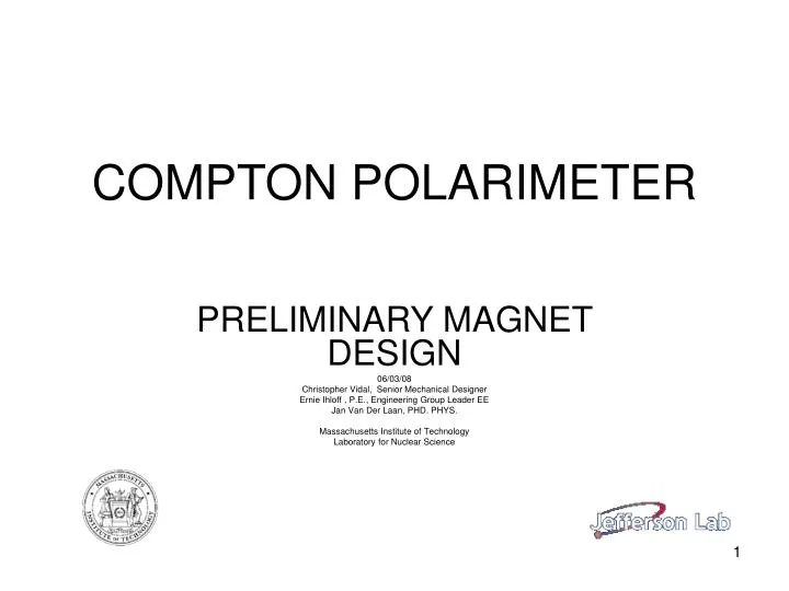
COMPTON POLARIMETER. PRELIMINARY MAGNET DESIGN 06/03/08 Christopher Vidal, Senior Mechanical Designer Ernie Ihloff , P.E., Engineering Group Leader EE Jan Van Der Laan, PHD. PHYS. Massachusetts Institute of Technology Laboratory for Nuclear Science. PRELIMINARY LAYOUT. LAYOUT DETAIL.

E N D
COMPTON POLARIMETER PRELIMINARY MAGNET DESIGN 06/03/08 Christopher Vidal, Senior Mechanical Designer Ernie Ihloff , P.E., Engineering Group Leader EE Jan Van Der Laan, PHD. PHYS. Massachusetts Institute of Technology Laboratory for Nuclear Science
MAGNET DESIGN SPEFICATIONS OVERALL LENGTH----------------------------------------------------141.64 CM (55.76 IN) EFFECTIVE LENGTH------------------------------------------------- 125.00 CM (49.21 IN) STEEL LENGTH-------------------------------------------------------- 121.48 CM (47.82 IN) OVERALL HEIGHT------------------------------------------------------ 60.34 CM (23.76 IN) STEEL HEIGHT-----------------------------------------------------------45.72 CM (18.00 IN) OVERALL WIDTH-------------------------------------------------------- 62.23 CM (24.50 IN) STEEL WIDTH-------------------------------------------------------------62.23 CM (24.50 IN) WEIGHT------------------------------------------------------------1294.75 KG (2854.44 LBS) POLE GAP---------------------------------------------------------------------3.00 CM (1.18 IN) TURNS PER COIL-------------------------------------------------------------------------------64 FIELD STRENGTH-------------------------------------5.58 KG @ 1.165 GeV, 10.3 Deg. 12.14 KG @11.023 GeV, 2.4 Deg.
SAMPLE DETAIL DRAWINGS 1: Detail drawings for the magnets have been sent to “New England Techni-Coil Inc.” In Wolfboro NH. A cost quote and lead time are pending. 2: Detail drawings for stands in process. Stands can be constructed at Bates. 3: Detail drawings for vacuum chambers in process. Chambers can be constructed at Bates. 4:Additional fabrication sources will be considered upon request. DRAWING SHOWN IN PRESENTATION MAY NOT BE LASTEST REV. AS DESIGNS MAY STILL BE IN PROGRESS
SUPPORT STANDS 1: Welded tubular steel construction. 2: Course height and level adjustments made via 4 leveling pads. 3: Fine positional adjustment made via 6 struts mounted to a removable plate. 4: Stands are designed to place center of magnet poles 57CM below beam height. 5: Different heights will be addressed with pedestals of similar construction.
VACUUM CHAMBER Chamber is constructed from 304 stainless steel with internal welds, where possible, 0r full penetration external welds where internal is not possible. The round flange uses a copper conflat gasket, and the rectangular flange uses an All metal “VAT” seal.
Final design drawings for the stands and connecting vacuum chambers will be completed upon approval of the preliminary magnet design. Trim coil design in progress. Strain relief for power and cooling connections needs to be designed Layout and designs could change pending a discussion regarding magnet poles which are parallel to the beam or poles with equal entrance and exit angles. Secondary pole tips need to be detailed to machine drawings for 12kG configuration. REMAINING DETAILS