Download
1 / 29
560 likes | 1.34k Views
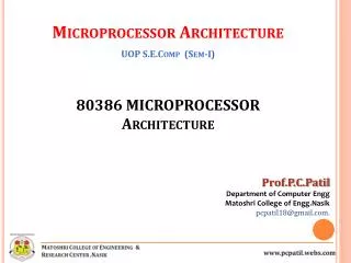
Intel 80386 MP. 80386 (32-bit microprocessor). Designed to overcome the limits of its predecessor while maintaining the software compatibility with the 8086 & earlier processors • Features: – 32 bit ALU – Segments can be as large as 4Gbytes – Total no. of segments possible: 16, 384

E N D
80386 (32-bit microprocessor) • Designed to overcome the limits of its predecessor while maintaining the software compatibility with the 8086 & earlier processors • Features: – 32 bit ALU – Segments can be as large as 4Gbytes – Total no. of segments possible: 16, 384 – Virtual address space is 16,384 X 4 = 64Tbytes of physical memory
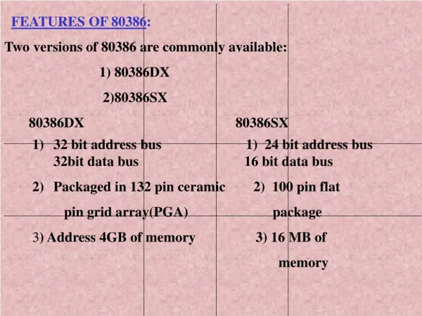
FEATURES OF 80386: Two versions of 80386 are commonly available: 1) 80386DX 2)80386SX 80386DX 80386SX • 32 bit address bus 1) 24 bit address bus 32bit data bus 16 bit data bus • Packaged in 132 pin ceramic 2) 100 pin flat • pin grid array(PGA) package • 3) Address 4GB of memory 3) 16 MB of • memory
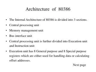
Architecture of 80386 • The Internal Architecture of 80386 is divided into 3 sections. • Central processing unit(CPU) • Memory management unit(MMU) • Bus interface unit(BIU) • Central processing unit is further divided into Execution unit(EU) and Instruction unit(IU) • Execution unit has 8 General purpose and 8 Special purpose registers which are either used for handling data or calculating offset addresses.
•The Instruction unit decodes the opcode bytes received from the 16-byte instruction code queue and arranges them in a 3- instruction decoded instruction queue. • The multiply / divide logic implements the bit-shift-rotate algorithms to complete the operations in minimum time. •Even 32- bit multiplications can be executed within one microsecond by the multiply / divide logic.
•The Memory management unit consists of • Segmentation unit and • Paging unit. • •Segmentation unit allows the use of two address components, viz. segment and offset for relocability and sharing of code and data. • •Segmentation unit allows segments of size 4Gbytes at max. • •The Paging unit organizes the physical memory in terms of pages of 4kbytes size each. • •Paging unit works under the control of the segmentation unit, i.e. each segment is further divided into pages. The virtual memory is also organizes in terms of segments and pages by the memory management unit.
Real operating mode • The 80386 has eight 32 - bit general purpose registers which may be used as either 8 bit or 16 bit registers. • A 32 - bit register known as an extended register, is represented by the register name with prefix E. • Example : A 32 bit register corresponding to AX is EAX, similarly BX is EBX etc. • The 16 bit registers BP, SP, SI and DI in 8086 are now available with their extended size of 32 bit and are names as EBP,ESP,ESI and EDI. • AX represents the lower 16 bit of the 32 bit register EAX. • BP, SP, SI, DI represents the lower 16 bit of their 32 bit counterparts, and can be used as independent 16 bit registers.
Real operating mode (cont..) • The six segment registers available in 80386 are CS, SS, DS, ES, FS and GS. • The CS and SS are the code and the stack segment registers respectively, while DS, ES, FS, GS are 4 data segment registers. • A 16 bit instruction pointer IP is available along with 32 bit counterpart EIP. • System Address Registers: Four special registers are defined to refer to the descriptor tables supported by 80386. • The 80386 supports four types of descriptor table, viz. global descriptor table (GDT), interrupt descriptor table (IDT), local descriptor table (LDT) and task state segment descriptor (TSS).
•Segment Descriptor Registers: This registers are not available for programmers, rather they are internally used to store the descriptor information, like attributes, limit and base addresses of segments. •The six segment registers have corresponding six 73 bit descriptor registers. Each of them contains 32 bit base address, 32 bit base limit and 9 bit attributes. These are automatically loaded when the corresponding segments are loaded with selectors. •Control Registers: The 80386 has three 32 bit control registers CR0, CR2 and CR3 to hold global machine status independent of the executed task. Load and store instructions are available to access these registers. •System Address Registers: Four special registers are defined to refer to the descriptor tables supported by 80386.
•Memory Addressing in Real Mode: In the real mode, the 80386 can address at the most 1 Mbytes of physical memory using address lines A0-A19. •Paging unit is disabled in real addressing mode, and hence the real addresses are the same as the physical addresses. •To form a physical memory address, appropriate segment registers contents (16-bits) are shifted left by four positions and then added to the 16-bit offset address formed using one of the addressing modes, in the same way as in the 80386 real address mode. •The segment in 80386 real mode can be read, write or executed, i.e. no protection is available. •The interrupt vector table of 80386 has been allocated 1Kbyte space starting from 00000H to 003FFH.
Protected Mode of 80386: •All the capabilities of 80386 are available for utilization in its protected mode of operation. •The 80386 in protected mode support all the software written for 80286 and 8086 to be executed under the control of memory management and protection abilities of 80386. •The protected mode allows the use of additional instruction, addressing modes and capabilities of 80386.
ADDRESSING IN PROTECTED MODE: In this mode, the contents of segment registers are used as selectors to address descriptors which contain the segment limit, base address and access rights byte of the segment. •The effective address (offset) is added with segment base address to calculate linear address. This linear address is further used as physical address, if the paging unit is disabled, otherwise the paging unit converts the linear address into physical address. •The paging unit is a memory management unit enabled only in protected mode. The paging mechanism allows handling of large segments of memory in terms of pages of 4Kbyte size.
•The paging unit operates under the control of segmentation unit. The paging unit if enabled converts linear addresses into physical address, in protected mode. Segmentation: •Descriptor tables:These descriptor tables and registers are manipulated by the operating system to ensure the correct operation of the processor, and hence the correct execution of the program. •Three types of the 80386 descriptor tables are listed as follows: •GLOBAL DESCRIPTOR TABLE ( GDT ) •LOCAL DESCRIPTOR TABLE ( LDT ) •INTERRUPT DESCRIPTOR TABLE ( IDT )
•Descriptors:The 80386 descriptors have a 20-bit segment limit and 32-bit segment address. The descriptor of 80386 are 8-byte quantities access right or attribute bits along with the base and limit of the segments.
Paging: •Paging Operation: Paging is one of the memory management techniques used for virtual memory multitasking operating system. •The segmentation scheme may divide the physical memory into a variable size segments but the paging divides the memory into a fixed size pages. •The segments are supposed to be the logical segments of the program, but the pages do not have any logical relation with the program. •The pages are just fixed size portions of the program module or data.
•The advantage of paging scheme is that the complete segment of a task need not be in the physical memory at any time. •Only a few pages of the segments, which are required currently for the execution need to be available in the physical memory. Thus the memory requirement of the task is substantially reduced, relinquishing the available memory for other tasks. •Whenever the other pages of task are required for execution, they may be fetched from the secondary storage. •The previous page which are executed, need not be available in the memory, and hence the space occupied by them may be relinquished for other tasks.
•Thus paging mechanism provides an effective technique to manage the physical memory for multitasking systems. •Paging Unit: The paging unit of 80386 uses a two level table mechanism to convert a linear address provided by segmentation unit into physical addresses. The paging unit converts the complete map of a task into pages, each of size 4K. The task is further handled in terms of its page, rather than segments. The paging unit handles every task in terms of three components namely page directory, page tables and page itself.
•Paging Descriptor Base Register: The control register CR2 is used to store the 32-bit linear address at which the previous page fault was detected. The CR3 is used as page directory physical base address register, to store the physical starting address of the page directory. The lower 12 bit of the CR3 are always zero to ensure the page size aligned directory. A move operation to CR3 automatically loads the page table entry caches and a task switch operation, to load CR0 suitably.
•Page Directory: This is at the most 4Kbytes in size. Each directory entry is of 4 bytes,thus a total of 1024 entries are allowed in a directory.The upper 10 bits of the linear address are used as an index to the corresponding page directory entry. The page directory entries point to page tables. •Page Tables: Each page table is of 4Kbytes in size and many contain a maximum of 1024 entries. The page table entries contain the starting address of the page and the statistical information about the page. •The upper 20 bit page frame address is combined with the lower 12 bit of the linear address. The address bits A12- A21 are used to select the 1024 page table entries. The page table can be shared between the tasks.
•The P bit of the above entries indicate, if the entry can be used in address translation. •If P=1, the entry can be used in address translation, otherwise it cannot be used. •The P bit of the currently executed page is always high. •The accessed bit A is set by 80386 before any access to the page. If A=1, the page is accessed, else unaccessed. •The D bit ( Dirty bit) is set before a write operation to the page is carried out. The D-bit is undefined for page director entries. •The OS reserved bits are defined by the operating system software.
•The User / Supervisor (U/S) bit and read/write bit are used to provide protection. These bits are decoded to provide protection under the 4 level protection model. •The level 0 is supposed to have the highest privilege, while the level 3 is supposed to have the least privilege. •This protection provide by the paging unit is transparent to the segmentation unit.
Paging (cont..) PAGE TABLE ENTRY
•In its protected mode of operation, 80386DX provides a virtual 8086 operating environment to execute the 8086 programs. •The real mode can also used to execute the 8086 programs along with the capabilities of 80386, like protection and a few additional instructions. •Once the 80386 enters the protected mode from the real mode, it cannot return back to the real mode without a reset operation. •Thus, the virtual 8086 mode of operation of 80386, offers an advantage of executing 8086 programs while in protected mode. •The address forming mechanism in virtual 8086 mode is exactly identical with that of 8086 real mode.
•In virtual mode, 8086 can address 1Mbytes of physical memory that may be anywhere in the 4Gbytes address space of the protected mode of 80386. •Like 80386 real mode, the addresses in virtual 8086 mode lie within 1Mbytes of memory. •In virtual mode, the paging mechanism and protection capabilities are available at the service of the programmers. •The 80386 supports multiprogramming, hence more than one programmer may be use the CPU at a time.
80386 instruction set Bit scan and test instructions • BSF bit scan to the left until nonzero bit is found • BSR bit scan to the right until nonzero bit is found • BT bit test and put specified bit in carry flag • BTC bit test and complement • BTR bit test and reset • BTS bit test and set
Data Type conversions • CDQ convert signed double word in EAX to quadword in EDX:EAX • CWDE convert signed word in AX to double word in entered EAX Segment Load instruction • LFS load FS segment register and specified base register with values from specified memory locations. • LGS load GS segment register and specified register from specified memory locations. • LSS Load SS segment register and specified register from specified memory locations
Move and expand instructions • MOVSX move and sign extend to fill destination register • MOVZX move and zero extend to fill destination register Set memory flag word instruction • SETXX set all bits in specified byte if condition xx is met. xx here can be any condition from conditional jump mnemonics. Shift between words • SHLD shift specified number of bits left from one operand into another • SHRD shift specified number of bits right from one operand into another