Download
1 / 61
610 likes | 939 Views
DIPARTIMENTO DI INGEGNERIA MECCANICA, NUCLEARE E DELLA PRODUZIONE UNIVERSITA' DI PISA 56100 PISA -ITALY. THE USE OF THE NATURAL CIRCULATION FLOW MAP. F. D’Auria , D. Araneo, B. Neykov – Lecture T20. IAEA & ICTP Course on NATURAL CIRCULATION IN WATER-COOLED NUCLEAR POWER PLANTS

E N D
DIPARTIMENTO DI INGEGNERIA MECCANICA, NUCLEARE E DELLA PRODUZIONE UNIVERSITA' DI PISA 56100 PISA -ITALY THE USE OF THE NATURAL CIRCULATION FLOW MAP F. D’Auria, D. Araneo, B. Neykov – Lecture T20 IAEA & ICTP Course on NATURAL CIRCULATION IN WATER-COOLED NUCLEAR POWER PLANTS Trieste, Italy, June 25-29 2007
2/61 Roadmap for the Training Course on NC in Water-Cooled Reactors
CONTENT 2/47 • NCFM DEFINITION AND ROLE • (CONNECTION WITH) THE SCALING ISSUE • DERIVATION OF THE NCFM (part of scaling activity) - The ITF - The NC BIC - The experimental scenario - The scale dependent parameters - The capability of the codes in predicting NC - The scale-up of data: 1 NC, use of TH codes, NC regimes - The NCFM • APPLICATION OF THE NCFM • CONCLUSION • APPENDIX 1: MAX POWER REMOVAL BY NC
THE NCFM DEFINITION AND ROLE 2/47 • THE NCFM ACRONYM: • NATURAL CIRCULATION FLOW MAP FOR PWR SYSTEMS • WHAT IS NCFM? • NCFM IS AN ‘ENGINEERING’ TOOL DERIVED FROM ITF MEASURED DATA • FOR 1 AND 2 NATURAL CIRCULATION • THE NCFM ROLE: • IT CAN BE USED TO SUPPORT: • SCALING STUDIES (but also derived from scaling related data) • DESIGN/OPTIMISATION OF NC SYSTEMS • VALIDATION OF COMPUTATIONAL MODELS (codes, nodalisation, etc.) • JUDGING THE NC PERFORMANCE
THE SCALING ISSUE 5/61 The framework: THE TRANSIENT PERFORMANCE OF LWR NPP (HIGH POWER, HIGH PRESSURE, LARGE GEOMETRY) The origin of the problem: THE IMPOSSIBILITY TO PERFORM RELEVANT EXPERIMENTS AT FULL SCALE (POWER, PRESSURE, GEOMETRY)
THE SCALING ISSUE 6/61 The goal of a scaling analysis TO ENSURE (OR TO SUPPORT) THE PREDICTABILITY OF LWR NPP TRANSIENT SCENARIOS The historical ways to address the issue • FLUID BALANCE EQUATIONS (deriving non-dimensional parameters) • SEMI-EMPIRICAL MECHANISTIC EQUATIONS (deriving non-dimensional parameters) • TO PERFORM EXPERIMENTS (at different scales) • TO DEVELOP, TO QUALIFY, TO APPLY CODES (by showing capabilities at different scales)
THE SCALING ISSUE 7/61 The target of a scaling analysis • THE GLOBAL SYSTEM PERFORMANCE (e.g. the prediction of pressure behavior during blow-down, following LOCA) • THE PERFORMANCE OF A COMPONENT OR OF A ZONE OF THE SYSTEM (e.g. pump performance during LBLOCA, or CL-DC mixing following ECCS injection) • THE ‘LOCAL’ EVOLUTION OF THERMALHYDRAULIC PHENOMENA (e.g. the CHF occurrence in fuel rods, the CCFL at the UTP following UP injection, the TPCF at the break) MACROSCALE COMPONENT SCALE MICROSCALE
THE SCALING ISSUE 8/61 The objectives of a scaling analysis • TO PROVE THE CAPABILITY IN SIMULATING AN ASSIGNED PHENOMENON • TO DESIGN A TEST FACILITY • TO PROVE THE SCALING CAPABILITY OF A TH MODEL OR OF A TH (SYSTEM) CODE
THE SCALING ISSUE 9/61 A SPECIAL ISSUE OF THE J. ‘NUCLEAR ENGINEERING AND DESIGN’ DEVOTED TO SCALING IN 1998 – MORE THAN 300 PAGES & 12 PAPERS • THREE LEVELS OF SCALING ANALYSIS PROPOSED BY ISHII et al.: • - Integral scaling • - Control volume scaling • - Local phenomena scaling • THE AUTHORS END UP WITH MORE THAN 200 SCALING FACTORS, BUT • “… The design cannot completely satisfy all the scaling requirements. thus, scaling distortions are inevitable … Distortions are encountered for two major reasons: • - difficulty to match the local scaling criteria • - lack of understanding of the local phenomenon itself.”
THE SCALING ISSUE 10/61 A SPECIAL ISSUE OF THE J. ‘NUCLEAR ENGINEERING AND DESIGN’ DEVOTED TO SCALING IN 1998 – MORE THAN 300 PAGES & 12 PAPERS • A SCALING STUDY WAS COMPLETED BY BANERJEE et al., FOCUSED ON THE ROSA, SPES AND OSU FACILITIES, THAT SIMULATE THE AP-600 NPP. ABOUT 30 SCALING PARAMETERS WERE FOUND. AN EXCERPT FROM A LARGER TABLE IS GIVEN. The scaling study identified phenomena in general agreement with the PIRT. Notwithstanding the differences in the table, “…the magnitude of the non-dimensional coefficients were similar for the ITF and the AP-600 … the same ‘important’ processes occurred in the ITF as might be expected in the AP-600.”
THE SCALING ISSUE 11/61 PURSUING A SYSTEMATIC APPROACH IMPLIES 1) ID and characterization of thermal-hydraulic phenomena 2) Writing equations (fluid balance & mechanistic) at macro-scale, component-scale and micro-scale levels and deriving suitable non-dimensional parameters 3) Achieving ‘qualified’ functional relationships between phenomena and scale B) SCALING APPROACHES AVAILABLE (Zuber, Ishii, etc.) C) COMPREHENSIVE SOLUTION NOT ACHIEVED YET (Ishii et al., J. NED 1998, see also below)
THE SCALING ISSUE 12/61 D) IN GENERAL TERMS: two-phase, transient TH phenomena, are affected by local system parameters that do not appear into balance equations or into ‘scalable’ mechanistic models: TPCF is affected (at least) by phenomena like ‘vapor pull through’ & sub-cooled vapor formation by ‘sharp edge cavitation’. These are not reproducible at a different scale. In addition, heat losses, mixture level formation and fluid temperature stratification cannot be scaled up.
THE SCALING ISSUE 13/61 E) THE ATTEMPT TO SCALE UP ALL TH PHENOMENA (e.g. TPCF, CCFL, nat. circ., CHF, DPi, ) RELEVANT DURING AN ASSIGNED TRANSIENT IN LWR NPP, IS UNSUCCESSFUL: • A myriad scaling factors • Counterfeiting values • THEREFORE, • HIERARCHY IN SCALING FACTORS (as recognized by Zuber) • AN OVERALL SCALING STRATEGY • ARE NEEDED
DERIVATION OF THE NCFM / THE ITF 14/61 THE ITF (AND THE NPP) AT THE ORIGIN OF THE NC DATABASE
DERIVATION OF THE NCFM / THE ITF 15/61 A MORE DETAILED VIEW OF A SINGLE ITF: THE LOBI/MOD2
DERIVATION OF THE NCFM / THE NC BIC 16/61 HARDWARE CHARACTERISTICS OF SELECTED ITF AND DOEL NPP
DERIVATION OF THE NCFM / THE NC BIC 17/61 BIC VALUES FOR SELECTED ITF EXPERIMENTS – 1 OF 2
DERIVATION OF THE NCFM / THE NC BIC 18/61 BIC VALUES FOR SELECTED ITF EXPERIMENTS – 2 OF 2 Quantities defined in previous slide; Including DOEL NPP
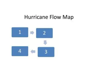
DERIVATION OF THE NCFM /THE EXP SCENARIO 19/61 THE NC SCENARIO FROM DRAINING PS MASS INVENTORY – 1 of 2 1 2 3 4 • Core Flowrate; 2) Mass Inventory and Rod Surface Temperature; • 3) DP oscillations; 4) Primary Pressure and SG DP
DERIVATION OF THE NCFM /THE EXP SCENARIO 20/61 THE NC SCENARIO FROM DRAINING PS MASS INVENTORY – 2 of 2 6 5 5) Density in HL; 6) Fluid velocities in IL and BL
DERIVATION OF THE NCFM /THE SCALE DEPENDENCE 21/61 THE PARAMETERS TO BE CONSIDERED IN SCALING 2 1 Kv5 Kv5 4 Kw/UT5 p 3 • & 2) PS volume; 3) Thermal load on individual U-Tubes (various L/D); • 4) PS pressure
DERIVATION OF THE NCFM /THE SCALE DEPENDENCE 22/61 THE PARAMETERS THAT HAVE SMALL SCALE EFFECT 2 1 3 4 • Length over diameter in HL; 2) Core power; 3) Presence of core bypass; • 4) Core active height
DERIVATION OF THE NCFM /THE CODE CAPABILITIES 23/61 THE TH SYS CODES ARE CAPABLE TO PREDICT RELEVANT NC PARAMETERS – TYPICAL NODALISATION SKETCH
DERIVATION OF THE NCFM /THE CODE CAPABILITIES 24/61 THE TH SYS CODES ARE CAPABLE TO PREDICT RELEVANT NC PARAMETERS – EXP/CALC BIC DATASET
DERIVATION OF THE NCFM /THE CODE CAPABILITIES 25/61 THE TH SYS CODES ARE CAPABLE TO PREDICT RELEVANT NC PARAMETERS – NODALISATION RESOURCES
DERIVATION OF THE NCFM /THE CODE CAPABILITIES 26/61 THE TH SYS CODES ARE CAPABLE TO PREDICT RELEVANT NC PARAMETERS 1 2 4 3 • Initial steady-state (fluid temperature vs length); 2) Density in HL vs time; • 3) DP across SG UT in PS vs time; 4) Core flowrate vs PS mass inventory.
DERIVATION OF THE NCFM /THE ATTEMPT TO SCALE-UP 27/61 A SIMPLIFIED APPROACH TO SCALE-UP 1 NC 1 2 3 4 Starting from the definition of driving and resistant forces (eqs. 1), one obtains an expression for core flowrate, eq. 4, that depends upon Kv and pressure drops (distributed and localized as given by the eq. 3 and the C6 coefficient in eq. 4).
DERIVATION OF THE NCFM /THE ATTEMPT TO SCALE-UP 11/61 A SIMPLIFIED APPROACH TO SCALE-UP 1 NC: RESULTS A core flowrate, function of Kv is derived (1 NC) and is compared with exp data & with results of code calculations.
DERIVATION OF THE NCFM /THE ATTEMPT TO SCALE-UP 29/61 A SIMPLIFIED APPROACH TO SCALE-UP 2 NC: RESULTS The attempt to scale-up 2 NC is not as succesfull: a) “extrapolation” formulas cannot be easily derived; b) the application of qualified code-nodalisation produces the results shown in the figures.
DERIVATION OF THE NCFM /THE NC REGIMES 30/61 THE (SCALE INDEPENDENT) NC REGIMES 4 5 1 2 3 1 NC, 2 NC and max 2 NC, 2 NC instabilities (siphon condensation), reflux condensation, dryout occurrence can be distinguished in the figure, items 1 to 5
DERIVATION OF THE NCFM / THE NCFM 31/61 THE ROUGH DATA GATHERING (TO DERIVE NCFM) Collecting of rough ITF data does not provide suitable information
DERIVATION OF THE NCFM / THE NCFM 32/61 THE DATA BASE HAS BEEN REPORTED IN THE “G/P VS RM/V” PLANE NCFM • The bounding of the database constitutes the NCFM. This is used for • scaling studies • design/optimisation of nc systems • validation of computational models (codes, nodalisation, etc.) • judging the NC performance
APPLICATION OF THE NCFM 1 PWR 2 PWR 3 PWR 4 VVER 5 EPR 6 AP-600 7 EP-1000 Nominal Power (MW) 1877 870 2733 3000 4250 1972 2958 Primary System volume (m3) 167 150 330 359 459 211 339 SG type U-Tubes U-Tubes Once-Through Horizontal U-Tubes U-Tubes U-Tubes No. of loops 2 4 2 4 4 2 3 No. of pumps 2 4 4 4 4 4 6 Nominal mass inventory (Mg) 108 108 224 240 307 145 227 Nominal Core Flow (Kg/s) 9037 3150 17138 15281 20713 8264 14507 Pressurizer and SG pressure (MPa) 15.6 6. 14.0 3.1 15.0 6.4 15.7 6.3 15.5 7.2 15.5 5.5 15.8 6.4 33/61 Characteristics of NPP considered for the application of the NCFM
APPLICATION OF THE NCFM 34/61 Characteristics of ITF considered for the application of the NCFM
APPLICATION OF THE NCFM 35/61 RESULT – 1 OF 3 The predicted NC performance of VVER-1000, PWR-NPP 2 and EPR is consistent with the derived NCFM. ‘Lower’ NCP for PWR-NPP 3.
APPLICATION OF THE NCFM 36/61 RESULT – 2 OF 3 The predicted NC performance of EP-1000, PWR-NPP 1 and AP-600 is consistent with the derived NCFM
APPLICATION OF THE NCFM 11/61 RESULT – 3 OF 3 Suitable NC performance is obtained for VVER-440 simulator and not for CANDU simulator
APPLICATION OF THE NCFM 11/61 SUMMARY OF RESULT Evaluation of NCP shall be considered together with quality of the available DB and of the adopted computational tools
APPLICATION OF THE NCFM 39/61 ATUCHA-1 PHWR – Ferreri et al. - Nodalisation for SET II
APPLICATION OF THE NCFM Power MW MOD - MOD line PRZ # RUN NOTES to Primary UP open volumes closes 1 Test26 5% - 59.1 No No Yes 2 Test27 4% - 47.3 No No Yes SET - I 3 Test28 3% - 36.1 No No Yes 4 Test30 2% - N o No Yes 5 Test31 3% - Yes No Yes 6 Test35 3% - Yes Yes Yes SET - II NA - S.A SET - II I 7 Test01 - N 3% - Yes Yes No . 8 Test36 5% - 55.5 Yes Yes Yes 9 Test33 4% - 47.3 Yes No Yes 10 Test34 3% 40/61 ATUCHA-1, Ferreri et al. SET - II - 35.9 Yes Yes Yes SET - I I I 11 Test02 - N 4% - 47.0 Yes Yes No NA - S.A. 12 Test03 - N 5% - 58.9 Yes Yes No SBLOCA 13 Test04 - N 3% - 35.9 Yes Yes No SET - II I Outline of performed calculations – NPP qualified Relap5 input deck is used to evaluate the NCP of the CNA-1
APPLICATION OF THE NCFM 11/61 ATUCHA-1 PHWR, Ferreri et al. Results from SET-I
APPLICATION OF THE NCFM 11/61 ATUCHA-1 PHWR, Ferreri et al. Results from SET-II
APPLICATION OF THE NCFM 11/61 ATUCHA-1 PHWR, Ferreri et al. Results from SET-III
APPLICATION OF THE NCFM 11/61 PKL III experiment F1.2. Del Nevo et al. (2006) Natural circulation maps
APPLICATION OF THE NCFM – BWR NC DATABASE 11/61 11/24 DATABASE FROM: NPP measurements (N), ITF (I) & Calculations (C) N C N C N N C N C C I 45/61
APPLICATION OF THE NCFM – BWR 11/24 BWR NPP DATA & RBMK qualified calculation NC 46/61
REVISITED RD-14m APPLICATION (CANDU RELATED) 47/61 Step 0: Development of Relap5 RD-14m nodalisation 1636 hydraulic nodes 11788 meshes for conduction heat transfer
REVISITED RD-14m APPLICATION (CANDU RELATED) 17/24 Step 1: Analysis of LBLOCA test B-9401 (IAEA framework) System (header 6) pressure Rod surface temperature PCT location 48/61
REVISITED RD-14m APPLICATION (CANDU RELATED) 11/24 Step 2: full demonstration of nodalization qualification “On-Transient” Level (by FFTBM) “Steady-state” level
REVISITED RD-14m APPLICATION (CANDU RELATED) 11/24 Step 3: Calculation of NC scenario Distinction between: SG NC (NCFM applicable) Ch-to-Ch NC (NCFM not applicable) “SG-NC” RM/V > ~ 500 Ch-to-Ch NC