Download
1 / 17
170 likes | 180 Views
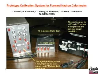
Online Calorimeter Calibration System. LAL-Orsay Patrick Cornebise, Pierre Imbert, Yves Jacquier, Gisèle Martin, Pierre Pétroff, Mélissa Riedel, Christophe de la Taille LPNHE-Paris

E N D
Online Calorimeter Calibration System LAL-Orsay Patrick Cornebise, Pierre Imbert, Yves Jacquier, Gisèle Martin, Pierre Pétroff, Mélissa Riedel, Christophe de la Taille LPNHE-Paris Philippe Bailly, Ursula Bassler, Gregorio Bernardi, Jean-François Huppert, Hervé Lebollo, Frédéric Machefert, Bob Olivier, Alain Vallerau
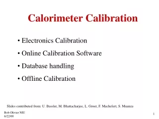
Electronics Calibration Calorimeter Electronics Trig. sum Bank 0 Calibration SCA (48 deep) SCA (48 deep) x1 Filter/ Shaper Output Buffer Preamp/ Driver SCA BLS x8 Calorimeter SCA (48 deep) SCA (48 deep) Bank 1 • intercalibration of cells and gain1, gain8 • estimate of absolute energy scale • calorimeter electronics commissioning: • bad channels • trigger verification • mapping
6 commandes (3x2) 96 courants VME Trigger Contrôleur de Pulse (pulser) Boîte de Préamp. Alimentation 2 Fanout (2x3x16 switchs) switch Calibration System
switches Calibration System: Active Fan-Out
Calibration System: Pulser Interface Board RAM Pulser 0 Pulser 0 L3 GUI Pulser 13 Pulser 13 Request Status CPU Transl Counter Serial Port Trigger Pulser
CALIB EXAMINE GUI for pulser setting (Bob) TAKER (Taka) COOR (Scott) datablock structure Hardware database VME address of RAM start COMICS (Alan) EPICS (Fritz) VBD (Dean) PIB (Frederic) program and protocol structure L3 (Mrinmoy) PULSER pulser control block
Software: GUI for Pulser Control • Pulsers Configuration to download: • signal height (DAC) • Enable for each pulser channel (patterns) • Commands • Delay • Calibration loop parameters: • linearity/timing • number of events per step • step size • pulser patterns
Performances: Linearity • ADC vs DAC (pulse height) • full ADC range covered at DAC=90k • linearity of calibration + calorimeter electronics better than 0.2% up DAC=65k • no significant noise added from the calibration system
pulse height increasingpulser delay time sampling time with respect to trigger -3 +3 +6 0 Performances: Pulse Shape em-channel had-channel • scanning pulse shape by varying delay • max response obtained for different delay values in em/had channels: • to be taken into account for pulser pattern determination • different runs at different delay values necessary • instability in the beginning of the pulse • effect of BLS visible
Performances: Pulser Uniformity • direct measurement of pulser currents over whole DAC range • fit of the slope for all channels of all pulsers 1 pulser: used for ICD Slope current/DAC Dispersion of slopes below 0.2% Dispersion of channels in one pulser below 0.1%
Performances: Pulser Uniformity • ADC vs DAC measurement of all pulsers in 5k-test with the same preamp card • measurement of slope for different preamps-types: • variations in slope between different pre-amp types • correct timing necessary for different types! (pulser patterns!) • uniformity by comparing measurements from all pulsers on same channel • better than 1% em A em D had
Performances: Cross-talk • cross-talk seen in neighboring channels: • ADC counts in pulsed channel varying by 28k • ADC counts in neighboring channel varying by 400 • cross-talk < 1.5%
Performances: Wave-form analysis • in situ “wave-form” measurements: • mapping and cabeling check • uniformity determination of complete final system: • correction factors • wave-form analysis: • determination of injected charge • method: • test card replace preamp motherboard • pulse read out on scope and analysed via GPIB interface • 8 folded pattern observed: • correction factors for effects of test-card, scope-gain and backplane
Performances: In-situ Linearity • observed linearity on amplitude better than 0.5% : • effects of scope gain visible • saturation at DAC > 60k • no corrections factors applied • to be studied: • integral • peak-time • decrease time
Performances: In-Situ Uniformity • slope amplitude vs. DAC determined for all channels of pulsers in CC/ECN • without corrections uniformity bettter than 1% • to be done: • measurements after installation completed (Oct 2000) • with preamp cards installed • determination of correction factors • determination of injected charge for charge/DAC correspondance
Schedule • Nov 98: first protopype tests Nov’98 • Fev-June’99: finalisation of design for Pulser and FanOut • July’99: cabeling CC/ECN • Oct’99: Fan Out installation CC/ECN • Dec’99: Pulser Installation • Jan-May 2000: tests and commissioning • June 2000: Pulser modification (filtering and grounding) Power Supply Installation Installation and cabeling of PIB • Sept-Oct 2000: Fan Out installation CC/ECS tests and commissioning • Software developpement