Download
1 / 76
770 likes | 1.03k Views
2008 ITRS Emerging Research Materials [ERM] December 6, 2008. Michael Garner – Intel Daniel Herr – SRC. ERM Workshops. ERM Workshops. Alternate Channel Materials WS III-V & Ge. Channel Structures and Materials: Heterostructure Integration Issues Current Approaches

E N D
2008 ITRSEmerging Research Materials[ERM]December 6, 2008 Michael Garner – Intel Daniel Herr –SRC
Alternate Channel Materials WSIII-V & Ge • Channel Structures and Materials: Heterostructure Integration Issues • Current Approaches • Direct growth of III-V Heterostructures on Silicon • III-V Growth on GeOI on Silicon (MIT) • Aspect Ratio trapping in III-V growth on silicon (Amber Wave, Takagi) • III-V Growth on GaAs-GeOI (Dual Logic) • Issues & Challenges • N- (III-V) and P- (Ge) channels growth of low-defect, strain-controlled films with acceptable mobilities after integration to silicon platforms • Reduction of dislocation densities – how low can we go? • Unusual crystallographic orientations are needed (best epi vs lowest DOS) • How do twins in ELO layers affect the carrier transport? • Are antiphase domains in III-V’s a problem for carrier transport? • Thickness level and control for lateral overgrowth and Ge condensation methods • Scaling of strain effects – for ultra-thin layers, can III-V’s support the elastic strain levels required without dislocating?
Alternate Channel Materials WSIII-V & Ge • Channel surface passivation and high-k dielectric deposition options • Current Approaches (III-V): • MBE Growth of III-V/Ga2O3/GdGaO Stack (Freescale) • As Cap/ In situ As decap +ALD HfO2 (Stanford) • NH4OH-ALD Al2O3 or HfO2 on III-V (Purdue) • InAlAs Barrier (MIT) • Current Approaches (Ge): • GeOxNy Nitridation (Stanford) • Ozone Oxidized Ge + ALD High κ dielectric HfO2 (Stanford) • LaGeOx-ZrO2(Ge) High K (Dual Logic)
High K Integration Issues • Wet (NH4S) vs dry (amorphous As cap) – shows importance of controlling surface oxidation effects on III-V’s to get lower Dit and unpinned interfaces. Sulfur passivation is not complete or stable compared to As cap. • Comparison of NH4OH to atomic H surface preparation during ALD of HfO2? • Comparison of a-Si cap vs a-As cap vs atomic hydrogen for III-V surface passivation and preparation? • GeOx nonstoichiometry is a major issue and can be controlled by either lower temperature ozone oxidation or forming gas anneals, or nitridation, or ----, before HfO2 deposition
S/D & Contact Formation • Current Approaches: • Ge • P-MOS: Boron with many ohmic metal contact options • N-MOS: Dopants have high diffusivity & metals schottky barriers • III-V • W contact/InGaAs cap/InAlAs (MIT) • Are barriers needed to keep dislocations out of the channel?
Carrier Transport Physics • How close are we to the theoretical ballistic scatting limit where all the channel mobilities are comparable? • What are the scattering mechanisms in ultra-thin channels? • are there new scattering sources (such as Coulomb scattering) other than phonon scattering that have yet to be discovered? • What role does alloy scattering play in III-V ternary and quaterenary alloys (e.g. InGaAs and AlInGaAs)?
Summary of Graphene Workshop I Toshiro Hiramoto, University of Tokyo (i) Prof. Ando, Theory of electric states and transport - Metallic transport! A universal conductivity at zero point due to scatterings. Bandgap opening is difficult. (ii) Dr. Tsukagoshi, Conduction control by gate voltage - Zero conduction (bandgap) observed in bilayer! (iii) Prof. Suemitsu, growth on Si substrate - Two layers of graphene films on SiC(111)/Si(110) (iv) Dr. Hibino, Evaluation of number of layers - Observation by nanogap (v) Prof. Kim, Graphene based nanoelectronics - High µ, edge effect, non-conventional devices
Inducing a Bandgap in Graphene • Applying an electric field to a multilayer graphene film can induce a bandgap • Ambipolar conduction peak can be shifted with high back gate voltage • Rate of the shift decreases exponentially with increasing graphene thickness • Gate induced charge density decreases with exponentially with screening thickness (λ~1.2nm) • K. Tsukagoshi
Bilayer Graphene • Next target wafer level multi layer graphene • Hiroki Hibino, NTT
Epitaxial graphene on Si substrate mediated by an ultra-thin SiC layer Prof. Suemitsu, Tohoku University
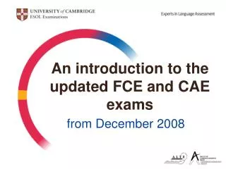
100 Eg (meV) Eg = E0 /(W-W0) 10 P1 P2 P3 P4 D1 D2 1 0 30 60 90 W (nm) Scaling of Energy Gaps in Graphene Nanoribbons Han, Oezyilmaz, Zhang and Kim PRL (2007)
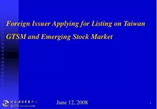
Son, et al, PRL. 97, 216803 (2006) Eg (meV) 2mm q (degree) 40 20 0 60 0 30 90 Graphene Nanoribbons Edge Effect Crystallographic Directional Dependence Rough Graphene Edge Structures
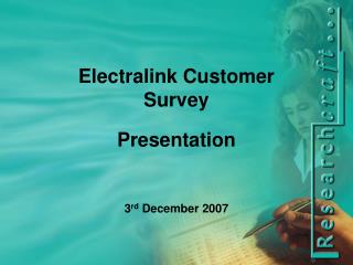
Mechanically exfoliated graphene TC17 Mobility (cm2/V sec) TC12 TC145 TC130 n (1012 cm-2) Mobility • Highest mobility for suspended graphene Tan et al. PLR (2007)
Graphene • Bi Layer Films enable field induced bandgap • Requires a high field (~109 V/cm) • Substrate effects reduce mobility
Graphene WS 2Integrable Deposition • CVD Growth of Graphene on Metal Substrates • Exfoliation • Tape • Graphene Oxidation • Solvent • SiC decomposition
Graphene CVD • The best substrates for high quality graphene are Pt 111 or Ni 111 and possibly Ir 111. • Graphene on Ni 111 was strongly chemisorbed onto a lattice matched substrate and had an undistorted structure that was aligned to the Ni • Both Pt 111 and Ir 111 (5d metals) are lattice mismatched to graphene • Graphene was undistorted in Pt and not aligned to the Pt surface • Graphene on Ir was slightly distorted
CVD Growth of Graphene on Ir • CVD growth of graphene on Iridium appears to be initiated at steps on surfaces resulting in island formation • The graphene appears to be continuous over steps • When the islands merge, this results in defects • Very slow growth (close to equilibrium) is required to produce high quality graphene
Scale up issues • Graphene can be transferred from Ni to an oxide substrate. • APPLIED PHYSICS LETTERS 93, 113103 (2008) • Bonded the graphene with silicone to a glass plate and etched away the metal substrate • A key challenge is that graphene is grown on high quality single crystal metal substrates (Pt, Ir, or Ni) and large diameter crystals are not available • Since nucleation occurs at steps, it may be difficult to grow high quality graphene on polycrystalline substrates. • Since the graphene is physisorbed onto Pt, this may be the most promising candidate for a polycrystalline substrate
Graphene Oxide DepositionC Gomez-Navarro and Vincent Tung • The conductivity of the graphene oxide increased 1000X upon exposure to: • Hydrazine for 24 hours • Hydrogen plasma 5 seconds • The mobility was measured to be between 10 and 1000cm2/V-sec. (~400-500 for UCLA) • Conduction was found to be dominated by hopping transport (CGN) • Graphene was found to have regions of highly ordered graphene surrounded by disordered graphene. • UCLA demonstrated the ability to selectively stack (physical transfer) layers of graphene on top of each other. • Maximum graphene flakes achieve to date are in the size range of 10μm to 100μm • Critical future work is to reduce the defect regions in the graphene by reducing the damage in the oxidation process.
Liquid Phase Exfoliation of GrapheneJonathan Coleman • Graphene can be exfoliated in solvents from HOPG with ultrasound, but solvent choices are limited because of solvent surface energy requirements. • The boiling point of the solvents is very high which makes deposition onto a substrate difficult • With NMP, 12% of the flakes in the solvent were monolayer graphene with most of the flakes being 1-3 layers thick. • 1% of the graphite was converted to monolayer graphene • The high boiling point of solvents allows graphene to reaggregate when trying to dry on a substrate • Further work is needed to establish a method to deposit the graphene on a surface from surfactant dispersed graphene in water or solvent.
Spin Materials Workshops • STT Structures • Electric Field Control of Spin and Magnetism • Ferromagnetic Semiconductors • Doped Oxides • Magnetoelectric Materials
STT Structures • MgO was a major breakthough in spin selection efficiency • Requires a 9A film thickness • Must be single crystal • May be limited options on interface materials • Major long term scaling issue is sputtering of ferromagnetic materials
Ferromagnetic Semiconductors • III-V (Mn doped) materials have been verified to have carrier mediated exchange with gated structures • 100-200K • Ferromagnetic behavior has been reported in GeMn nanostructures • Magnetometer & Anomalous Hall Effect • Not verified with gated structure • Is it possible to raise III-V Mn Tc to room temperature • Mark van Schlifgaard: Not with random doping, but possible with superlattices
Oxide Doped FM Materials • ZnO doped with Co, Mn is FM above room temperature • Ferromagnetism correlated with carrier concentration • Low mobility makes anomalous Hall effect difficult • In2O3: 2% Cr is FM with electron concentration above 2E19 cm-3 • Anomalous Hall effect observed
Oxide Doped FM MaterialsChallenges • Demonstrate stronger, detailed correlation of FM order with carrier density • Gated structures • Directly demonstrate and measure carrier spin polarization • spin-LEDs, TMR device, etc • Improve remanent magnetization (currently pathetic) • large remanence is critical • low remanence = weak exchange, low anisotropy, …??? • MFM indicates complex domain structure in Cr:In2O3 • Theoretical treatment has improved dramatically, needs to go further • band-gap corrected treatment provides more realistic picture • needs exp input on defect structure, levels r/t CMB,VBM, etc to even begin a detailed treatment
Magnetoelectric Materials • BiFeO3 Exchange Bias with CoFe couples electric polarization with magnetization • BFO is Ferroelectric and antiferromagnetic • Domain wall orientation and concentration played a key role in exchange bias (109°) • 109° domain walls were found to be conductive & possibly metallic • Proposed domain wall logic • Changing the FE polarization rotated the FM alignment of the CoFe structure • LSMO on BFO had an increased coercive field and shifted exchange bias with change of FE polarization.
Emerging Research Materials 2009 • Establish ERM Outline and Writing Assignments • Refine Critical Assessment Process • CMOS Extension: More detailed • Beyond CMOS: Trends on critical materials & properties • Update Key Challenges Tables • Plan Workshops on ERM • All workshops should identify Metrology, Modeling and ESH support as appropriate • Finalize new materials needs based on ITWG inputs • ERD, Lithography, FEP, Interconnects, Assembly & Packaging, PIDS • Establish Concrete targets • Functional Diversification
ERM Outline • Introduction • Difficult Challenges • Challenges for Multi-application ERM (Back-up?) • Materials for Alternate Channel CMOS (PIDS & ERD) • Critical Assessment • ERM for Beyond CMOS (ERD) • ERM for Lithography • Resist (pixilated, Multi photon resist, novel) • Self Assembled Materials • Transition Table (Molecular glasses, evolutionary resist macromolecular design, etc.) • ERM for FEP & PIDS • Deterministic Doping • Self Assembly for Selective Deposition & Etch • ERM for Interconnects • ERM for Assembly & Package • ERM ESH Research Needs • ERM Metrology Needs • ERM Modeling Needs
Challenges for Multi-application ERM • LDM • Control of placement & direction • Control of nanostructure, properties & macro properties • Macromolecules • Self Assembled Materials • Complex metal oxides
Materials for Alternate Channel CMOS • III-V & Ge (John Carruthers) • Semiconductor Nanowires (Ted Kamins) • Graphene (Daniel Beneshal) • Carbon Nanotubes (Jean Dijon)
Fundamental Alternate Channel Common Question • Does ballistic transport dominate over intrinsic mobility?
III-V & Ge Key Messages • Gate Dielectric Growth techniques are being developed • Current Approaches (III-V): • MBE Growth of III-V/Ga2O3/GdGaO Stack (Freescale) • As Cap/ In situ As decap +ALD HfO2 (Stanford) • NH4OH-ALD Al2O3 or HfO2 on III-V (Purdue) • InAlAs Barrier (MIT) • Current Approaches (Ge): • GeOxNy Nitridation (Stanford) • Ozone Oxidized Ge + ALD High κ dielectric HfO2 (Stanford) • LaGeOx-ZrO2(Ge) High K (Dual Logic) • Controlling surface oxide formation is critical for control of interface states • Control of interface stochiometry, structure and defects is critical • GeOx stochiometry control affected by growth temperature
III-V & Ge Key Messages • Ge dopant activation requires high temperature • Incompatible with III-V process temperatures • S/D Contact Formation Current Approaches: • Ge • P-MOS: Boron with many ohmic metal contact options • N-MOS: Dopants have high diffusivity & metals form Schottky barriers • III-V • W contact/InGaAs cap/InAlAs (MIT) • Are barriers needed to keep dislocations out of the channel?
III-V Ge Heteroepitaxy Challenges • Reduction of dislocation densities • Control of stress in III-V & Ge integrated on Si • Ultrathin films • Heterostructures to reduce defects • Effect of antiphase domains on carrier transport • Identify a crystal orientation that favors epitaxy and interface states.
Graphene Challenges & Status • Ability to deposit graphene on appropriate substrates • Producing a bandgap • Fabricating Narrow Graphene Lines • Applying a high electric field to bi-graphene • Achieving high mobility in an integrated structure • Achieving a high on-off conduction ratio
Graphene Deposition • CVD of Graphene on Ni, Pt, and Ir • Graphene is strongly bonded to Ni, but has a lattice match • Graphene deposited on Pt is not distorted, is not lattice matched, but is weakly bonded • SiC decomposition • Issue: High process temperature (>1100C) • Exfoliation Techniques • Graphene Oxide Decomposition (Mobility <1000cm2/V-sec) • Oxidation process produced islands of graphene surrounded by disordered material (hoping conduction) • Try less aggressive oxidation process • Solvent exfoliation • Solvents capable of separating graphene sheets are difficult to evaporate (high boiling point) • Tape exfoliation
Producing a Graphene Bandgap • Fabricating Narrow Graphene Lines • Requires patterning sub 20nm lines • Edge defect control is challenging (Eg & Mobility) • Applying a high electric field to bi-graphene • Field ~1E9 V/cm
Graphene Mobility • Mobility on substrates is reduced • Graphene Oxide Mobility • Degraded by disordered regions
Beyond CMOSM. Garner • Molecular State (Alex Bratkovski & Curt Richter) • Spin Materials (Kang Wang) • FM Semiconductors • CNT & Graphene • Tunnel Barriers • STT-Dr. Yeo • FM metals • Multiferroics • Complex Metal Oxides (TBD) • Ferroelectrics (Memory) • Tunnel Barrier
Memory Materials • Memory Materials • Professor H.S. Hwang
Molecular Devices • Top contact formation is still a significant issue • Determining that switching is due to the molecular energy levels is difficult
Spin Materials • Ferromagnetic III-V (Mn) semiconductors have verified Curie temperatures 100-200K • Carrier mediated exchange • Nanowires of GeMn have reported ferromagnetic properties at 300K+, but carrier mediated exchange with gated structure is difficult to verify • Oxides doped with transition metals have ferromagnetic properties • Ferromagnetism is determined by carrier doping, but it isn’t clear whether this can be modulated with electric fields • Ferromagnetism is proposed to be in an impurity band vs. the oxide bands. • It is not clear whether this is useful for device applications
Spin Materials (Cont.) • Spin Tunnel Barrier Materials • MgO crystalline material is the best spin selective tunnel barrier to date • May work with a limited number of materials due to lattice match requirement • Films must be ~9A thick • Al2O3 films work, but with much lower selectivity • Multiferroics • BaFeO3 has ferroelectric & ferromagnetic properties coupled • Limited degrees of freedom & low coupling
ERM for Lithography(Dan Herr & Joe Gordon) • ERM for Patterning • Novel Macromolecules for Resist • Multi wavelength resist (Dual exposure) (Transition in?) • Pixellated resist • Novel Macromolecules for CEL • Multi wavelength CEL (Dual Exposure) (Transition in?) • DSA Materials • Imprint molecules • Functional materials • ERM for Immersion Fluids • Nanoparticles for immersion fluids (Transition Table?)


![2011 ITRS Emerging Research Materials [ERM] July 10-13, 2011](https://cdn2.slideserve.com/4220097/2011-itrs-emerging-research-materials-erm-july-10-13-2011-dt.jpg)