Download
1 / 24
240 likes | 247 Views
This presentation illustrates the assembly process of JPARC Horn 2, featuring welding instead of bolting for the final step and the use of water seals. It includes steps such as lowering the IC into OC, making one end of the horn water-tight, rotating the horn, adding a ceramic ring, assembling studs, assembling a flange, compressing water seals, making the final weld connection, and attaching corona balls.

E N D
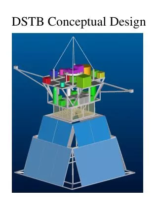
Conceptual design of JPARC Horn 2 assembly L. Bartoszek Bartoszek Engineering/CU 5/5/04
Assembly Scenario • The pictures in this presentation show an assembly scheme for Horn 2 which parallels that of the MiniBooNE horn with a significant exception • The last assembly step requires welding instead of bolting and is caused by the thin end cap region
Step 1: Lower IC into OC • The fixture for welding the IC is not shown • I did not spend time on figuring out the segments of the IC or the welding process • This scenario starts after all but the last weld is done
Step 2: Make one end of horn water tight • I assume a bolted connection at the end of the horn opposite the strip line, but it could be welded. • Water and current-carrying seals are not shown here
Step 3: Rotate horn 180 degrees • MiniBooNE rotated the horn to make measurements that allowed us to cut the last piece so that when the horn was bolted together the IC was in a state of zero stress—no tension or compression prior to pulsing • Rotating also allows the final operations to be done from on top instead of below—easier and safer
Fixtures needed to hold inner conductor to outer prior to rotating the horn on the rotating fixture Photos show the MiniBooNE fixtures Water ports make handy places to mount fixturing between the inner and outer conductors
Step 4: Add ceramic ring • The ceramic ring isolates the inner and outer conductors where the stripline connects to the horn • MiniBooNE made a lifting fixture for the ring because it was too heavy for people on ladders • Also put water seals in at this end (not shown)
Step 5: Assemble studs • Ceramic tubes isolate the fasteners that clamp the inner and outer conductors to the ceramic ring • A ceramic pin was used in MiniBooNE to cause angular alignment between pieces. May not need it here
Step 6: Assemble flange • This flange must be welded to the inner conductor to allow current from the stripline to make a complete circuit • MiniBooNE’s upstream flange could be bolted because it was thick • This flange is too thin to bolt
The thickness of the upstream end of the MiniBooNE horn allowed a bolted connection between the flange and the inner conductor
Step 7: Compress water seals • More ceramics are used as insulating washers to compress the flange to the outer conductor, squeezing the water seals and the ceramic ring • All ceramics are used in compression where they have significant strength • I cannot recommend putting ceramics in tension
Step 8: Final weld connection • Once the water seals on both sides of the ceramic ring are tight the last weld that connects the flange to the inner conductor can be done • The weld prep on the flange can only be cut after the final length of the inner conductor is known (after weld shrinkage)
Step 9: Corona ball assembly • The threaded rods have sharp edges that could cause breakdown with the high voltage of the stripline • The solid model does not show these edges on the threads • Corona balls hide the sharp edges and prevent corona discharge
Ready for attachment to striplines • At this point the horn can be mounted to its support module and fitted out with water nozzles, stripline connections and everything else