Download
1 / 94

E N D
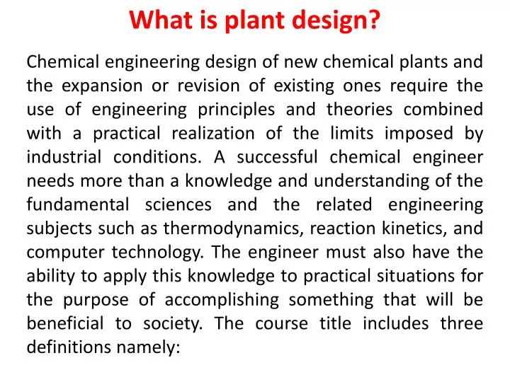
What is plant design? Chemical engineering design of new chemical plants and the expansion or revision of existing ones require the use of engineering principles and theories combined with a practical realization of the limits imposed by industrial conditions. A successful chemical engineer needs more than a knowledge and understanding of the fundamental sciences and the related engineering subjects such as thermodynamics, reaction kinetics, and computer technology. The engineer must also have the ability to apply this knowledge to practical situations for the purpose of accomplishing something that will be beneficial to society. The course title includes three definitions namely:
Definition of design 1. Design: design is a creative activity and is defined as the synthesis, the putting together of ideas to achieve a desired purpose. Also it can be defined as the creation of manufacturing process to fulfill a particular need. The need may be public need or commercial opportunity. 2. Process Design: Process design establishes the sequence of chemical and physical • operations; operating conditions; the duties, major specifications, and materials of construction (where critical) of all process equipment (as distinguished from utilities and building auxiliaries); the general arrangement of equipment needed to ensure proper functioning of the plant; line sizes; and principal instrumentation. The process design is summarized by a process flowsheet.
Process Design Steps 1. Flowsheetdevelopment. 2. Process material and heat balances. 3. Auxiliary services material and heat balances (utilities requirements). 4. Chemical engineering performance design for specific items of equipments required for a flowsheet. 5. Instrumentation as related to process performance. 6. Preparation of specifications (specification sheets) in proper form for use by the project team as well as for the purchasing function. 7. Evaluation of bids and recommendation of qualified vendor.
3. Plant Design: includes items related directly to the complete plant, such as plant layout, general service facilities, and plant location.
Design Development Stages Figure (2.1), The design process
The Design Objectives (The Need) Chemical engineering projects can be divided into three types: A. New process development. B. New production capacity to meet growing sales. C. Modification and addition to existing plant. In the design of a chemical process the need is the public need for the product, the commercial opportunity as foreseen by the sales and marketing organization. Setting the Design Basis (Data Collection) The most important step in starting a process design is translating the customer need into a design basis. The design basis is a more precise statement of the problem that is to be solved. It will normally include the production rate and purity specifications of the main product, together with information on constraints that will influence the design, such as:
1. Information on possible processes and the system of units to be used. 2. The national, local or company design codes that must be followed. 3. Details of raw materials that are available. 4. Information on potential sites where the plant might be located, including climate data, seismic conditions, and infrastructure availability. 5. Information on the conditions, availability, and price of utility services such as fuel (gas), steam, cooling water, process air, process water, and electricity, that will be needed to run the process.
Generation of Possible Design Concepts (Solutions) It is the creative part of the design process. This part is concerned with the generation of possible solutions for analysis, evaluation, and selection (ways of meeting objective problems). Source of solutions: a- Past experiences. b- Tried and tested methods.
Build Performance Model and Fitness Testi When design alternatives are suggested, they must be tested for fitness of purpose. In other words, the design engineer must determine how well each design concept meets the identified need. In the field of chemical engineering, it is usually prohibitively expensive to build several designs to find out which one works best (a practice known as “prototyping” which is common in other engineering disciplines). Instead, the design engineer builds a mathematical model of the process, usually in the form of computer simulations of the process, reactors, and other key equipment. In some cases, the performance model may include a pilot plant or other facility for predicting plant performance and collecting the necessary design data.
The design engineer must assemble all of the information needed to model the process so as to predict its performance against the identified objectives. For process design this will include information on possible processes, equipment performance, and physical property data. If the necessary design data or models do not exist, then research and development work is needed to collect the data and build new models. Once the data has been collected and a working model of the process has been established, then the design engineer can begin to determine equipment sizes and costs. At this stage it will become obvious that some designs are uneconomical and they can be rejected without further analysis. From this step a few candidate designs that meet the customer objective are identified.
Economic Evaluation, Optimization, and Selection Once the designer has identified a few candidate designs that meet the customer objective, then the process of design selection can begin. The primary criterion for design selection is usually economic performance, although factors such as safety and environmental impact may also play a strong role. The economic evaluation usually entails analyzing the capital and operating costs of the process to determine the return on investment.
The economic analysis of the product or process can also be used to optimize the design. Every design will have several possible variants that make economic sense under certain conditions. For example, the extent of process heat recovery is a tradeoff between the cost of energy and the cost of heat exchangers (usually expressed as a cost of heat exchange area). In regions where energy costs are high, designs that use a lot of heat exchange surface to maximize recovery of waste heat for reuse in the process will be attractive. In regions where energy costs are low, it may be more economical to burn more fuel and reduce the capital cost of the plant.
When all of the candidate designs have been optimized, the best design can be selected. Very often, the design engineer will find that several designs have very close economic performance, in which case the safest design or that which has the best commercial track record will be chosen. At the selection stage an experienced engineer will also look carefully at the candidate designs to make sure that they are safe, operable, and reliable, and to ensure that no significant costs have been overlooked.
Detailed Design and Equipment Selection Here the detailed specifications of equipment such as vessels, exchangers, pumps, and instruments are determined. During the detailed design stage there may still be some changes to the design, and there will certainly be ongoing optimization as a better idea of the project cost structure is developed. The detailed design decisions tend to focus mainly on equipment selection though, rather than on changes to the flowsheet. For example, the design engineer may need to decide whether to use a Utube or a floating-head exchanger, or whether to use trays or packing for a distillation column.
Procurement, Construction, and Operation When the details of the design have been finalized, the equipment can be purchased and the plant can be built. Procurement and construction are usually carried out by an EPC firm (Engineering, Procurement, and Construction) unless the project is very small. Because they work on many different projects each year, the EPC firms are able to place bulk orders for items such as piping, wire, valves, etc., and can use their purchasing power to get discounts on most equipment. The EPC companies also have a great deal of experience in field construction, inspection, testing, and equipment installation. They can therefore normally contract to build a plant for a client cheaper (and usually also quicker) than the client could build it on its own. Finally, once the plant is built and readied for startup, it can begin operation. The design engineer will often then be called upon to help resolve any startup issues and teething problems with the new plant.
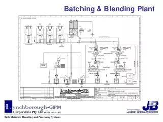
Flowsheeting(special language conveying information) Process design normally starts with a process scheme (flowsheet). The flowsheetis the key document or road map in process design. It's a diagrammatic model of the process describe the process steps in a proper sequence using symbols to represent the various components (equipment, lines, and control instrumentation) that make up the unit.
The Flowsheet Importance • Shows the arrangement of the equipment selected to carry out the process. • Shows the streams concentrations, flow rates & compositions. • Shows the operating conditions. • During plant start up and subsequent operation, the flow sheet from a basis for comparison of operating performance with design. It's also used by operating personnel for the preparation of operating manual and operator training.
FlowsheetPresentation 1- Block diagram • Represent the process in a simplified form. • No details involved. • Don’t describe how a given step will be achieved. • When is it used? • In survey studies. • Process proposal for packaged steps. • Talk out a processing idea.
2- Pictorial Flow Sheet The equipments are normally drawn in a stylized pictorial form. For tender documents or company brochures actual scale drawing of the equipment are sometimes used. Types of pictorial flowsheets a) Process Flow Diagram (PFD) A PFD is a simplified flow diagram of a single process unit, a utility unit, a complete process module. The purpose of a PFD is to provide a preliminary understanding of the process system indicating only the main items of equipment, the main pipelines and the essential instruments, switches and control valves.
A PFD also indicates operating variables, such as mass flow, temperatures and pressures, which are tabulated at various points in the system. The PFD is a document containing information on: • Process conditions and physical data of the main process streams. • Main process equipment with design data. • Main Process lines. • Mass (material) balance. • Heat balance (if applicable). NOTE: If the PFD doesn’t contain any data about the flow rates, it is called a qualitative flowsheet, while if the flow rates are involved the PFD is called a combined flowsheet in which qualitative information and quantitative data are combined on the basis of one flowsheet.
b) Piping and Instrumentation Diagram (P & ID) (mechanical flow diagram) A P&ID diagram shows the arrangement of the process equipment, piping, pumps, instruments, valves and other fittings. It should include: • All process equipment identified by an equipment number. • All pipes identified by a line size, material code and line number. • All valves with an identified size and number. • Fittings. • All pumps identified by a suitable code number. • All control loops and instruments.
c) Utility Flowsheet (Process Engineering Utility Flow Diagram (PEUFD)) Used to summarize and detail the interrelationship of utilities such as air, water (various types), steam (various types), heat transfer mediums, process vents and purges, safety relief blow-down, etc., to the basic process. The amount of detail is often too great to combine on other sheets, so separate sheets are prepared. The PEUFD is a document containing information on: Main distribution or arrangement of each individual utility system, expect electrical systems.
PEUFD Function: The PEUFD shall state characteristics and consumption figures of the particular utility concerned, cooling water, fire water, drinking water, steam, plant air, instrument air, fuel oil/gas, inert gas and similar utilities. d) Process Safeguarding Flow Diagram (PSFD) The PSFD is a document highlighting information on: Types and levels of protection offered by the devices installed and their inter relation to demonstrate the plant’s safety.
The P&ID contains all information required for a PSFD; however, the PSFD highlights protection in case of extreme conditions and measures to be taken to safeguard personnel and environment. Note: In general these schemes will only be made for complex installations like offshore process platforms. For simple applications the information shown on the P&ID is usually sufficient to highlight safety devices and aspects.
What is meant by the following identifications? PFD, P&ID, PEUFD and • PSFD State the information you can get from the following schemes: PFD, P&ID, PEUFD and PSFD?
Figure (2.3), PFD [Qualitative flow diagram for the manufacture of nitric acid by the ammonia-oxidation process]
Figure (2.4), PFD [Combined flow diagram for the manufacture of nitric acid by the ammonia-oxidation process]
Figure (2.7), Engineering P&I flowsheet of the reaction section of plant for dealkylationof benzene
FlowsheetSymbols To reduce detailed written descriptions on flowsheets, it is usual practice to develop or adopt a set of symbols and codes which suit the purpose. Many symbols are pictorial which is helpful in representing process as well as control and mechanical operations. See Fig. (2.8). Line Symbols and Designation The two types of lines on a flowsheet are (1) those representing outlines and details of equipment, instruments, etc., and (2) those representing pipe carrying process or utility liquids, solids, or vapors and electrical or instrument connections. The latter must be distinguished among themselves as suggested by Fig. (2.9).
The usual complete line designation contains the following: (1) line size (nominal); (2) material cod; (3) sequence number; and (4) materials of construction. Examples: 2"-CL6-CS40 3"-CL6a-CS40 Equipment Designation Equipment code designations can be developed to suit the particular process, or as is customary a master coding can be established and followed for all projects. A suggested designation list (not all inclusive for all processes) for the usual process plant equipment is given in Table (2.1). The various items are usually numbered by type and in process flow order as set forth on the flowsheets. For example:
Item code Designation • S-1 First separator in a processs • S-2 Second separator in a process • C-1 First compressor in a process
Types of Designs The methods for carrying out a design project may be divided into the following classifications, depending on the accuracy and detail required: Preliminary or quick-estimate designs Used as a basis for determining whether further work should be done on the proposed process. This type of design is based on approximate process methods, and rough cost estimates are prepared. Few details are included, and the time spent on calculations is kept at a minimum.
Detailed-estimate designs In this type of design, the cost and profit potential of an established process is determined by detailed analysis and calculations. However, exact specifications are not given for the equipment, and drafting-room work is minimized. The following factors should be established within narrow limits before a detailed-estimate design is developed: • Manufacturing process • Material and energy balances • Temperature and pressure ranges
Raw-material and product specifications • Yields, reaction rates, and time cycles • Materials of construction • Utilities requirements • Plant site • i.e. the above factors should be determined after a preliminary design.
Before proceeding any further with the development of a process design and its associated economics, it will be desirable to consider an overall view of the various functions involved in a complete plant design. Particular emphasis in this discussion will be placed on important health, safety, loss prevention, and environmental considerations. Other items that will be noted briefly include plant location, plant layout, plant operation and control, utilities, structural design, storage, materials handling, patents, and legal restrictions.
I. Plant Location The geographical location of the final plant can have strong influence on the success of an industrial venture. Considerable care must be exercised in selecting the plant site, and many different factors must be considered. Primarily, the plant should be located where the minimum cost of production and distribution can be obtained, but other factors, such as room for expansion and safe living conditions for plant operation as well as the surrounding community, are also important.
A general consensus as to the plant location should be obtained before a design project reaches the detailed estimate stage, and a firm location should be established upon completion of the detailed-estimate design. The choice of the final site should first be based on a complete survey of the advantages and disadvantages of various geographical areas and, ultimately, on the advantages and disadvantages of available real estate. The following factors should be considered in selecting a plant site:
1. Raw materials availability 2. Markets 3. Energy availability 4. Climate 5. Transportation facilities 6. Water supply 7. Waste disposal 8. Labor supply 9. Taxation and legal restrictions 10. Site characteristics 11. Flood and fire protection 12. Community factors
The factors that must be evaluated in a plant-location study indicate the need for a vast amount of information, both quantitative (statistical) and qualitative. Fortunately, a large number of agencies, public and private, publish useful information of this type greatly reducing the actual original gathering of the data. Raw materials availability: The source of raw materials is one of the most important factors influencing the selection of a plant site. This is particularly true if large volumes of raw materials are consumed, because location near the raw materials source permits considerable reduction in transportation and storage charges. Attention should be given to the purchased price of the raw materials, distance from the source of supply, freight or transportation expenses, availability and reliability of supply, purity of the raw materials, and storage requirements.
Markets: The location of markets or intermediate distribution centers affects the cost of product distribution and the time required for shipping. Proximity to the major markets is an important consideration in the selection of a plant site, because the buyer usually finds it advantageous to purchase from nearby sources. It should be noted that markets are needed for by-products as well as for major final products. Energy availability: Power and steam requirements are high in most industrial plants, and fuel is ordinarily required to supply these utilities. Consequently, power and fuel can be combined as one major factor in the choice of a plant site. Electrolytic processes require a cheap source of electricity, and plants using electrolytic processes are often located near large hydroelectric installations. If the plant requires large quantities of coal or oil, location near a source of fuel supply may be essential for economic operation. The local cost of power can help determine whether power should be purchased or self-generated.
Climate: If the plant is located in a cold climate, costs may be increased by the necessity for construction of protective shelters around the process equipment, and special cooling towers or air-conditioning equipment may be required if the prevailing temperatures are high. Excessive humidity or extremes of hot or cold weather can have a serious effect on the economic operation of a plant, and these factors should be examined when selecting a plant site.
Transportation facilities: Water, railroads, and highways are the common means of transportation used by major industrial concerns. The kind and amount of products and raw materials determine the most suitable type of transportation facilities. In any case, careful attention should be given to local freight rates and existing railroad lines. The proximity to railroad centers and the possibility of canal, river, lake, or ocean transport must be considered: Motor trucking facilities are widely used and can serve as a useful supplement to rail and water facilities. If possible, the plant site should have access to all three types of transportation, and, certainly, at least two types should be available. There is usually need for convenient air and rail transportation facilities between the plant and the main company headquarters, and effective transportation facilities for the plant personnel are necessary.
Water supply: The process industries use large quantities of water for cooling, washing, steam generation, and as a raw material. The plant, therefore, must be located where a dependable supply of water is available. A large river or lake is preferable, although deep wells or artesian wells may be satisfactory if the amount of water required is not too great. The level of the existing water table can be checked by consulting the state geological survey, and information on the constancy of the water table and the year-round capacity of local rivers or lakes should be obtained. If the water supply shows seasonal fluctuations, it may be desirable to construct a reservoir or to drill several standby wells. The temperature, mineral content, silt or sand content, bacteriological content, and cost for supply and purification treatment must also be considered when choosing a water supply.