Download
1 / 13
150 likes | 386 Views
Thin Wafer Handling Robot. Jordan Hall, Fang Li, Joel Neff, and Alex Podust. Background Handling of thin silicon wafers for solar cells Reducing handling stress and characterizing residual stresses are part of manufacturing research Objective

E N D
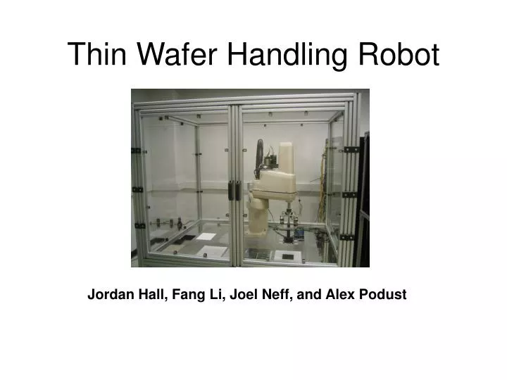
Thin Wafer Handling Robot Jordan Hall, Fang Li, Joel Neff, and Alex Podust
Background • Handling of thin silicon wafers for solar cells • Reducing handling stress and characterizing residual stresses are part of manufacturing research • Objective • Design a robot to move wafers between conveyor and inspection station without dropping or imposing large gripping forces • Minimize energy consumption and handling time
Bernoulli Gripper Model • Used an mass flow input to create a vertical “lift” force • Gripper force depends on distance to wafer • Rubber pads keep wafer from impacting gripper frame • The friction of the pads keeps wafer “stuck” to the gripper as the robot accelerates
Gripper – Modelica Code Gripper Force Balance Friction force is only active when the wafer is contacting the posts
Gripper - Verification Wafer separates Wafer Pick-up
Gripper Model Challenges Fgripper Ffriction • Required text-based Modelica modeling • No MultiBody sliding friction model • Required pneumatic->mechanical energy conversion • Force balance and direction vectors defined “from scratch.” • Interaction between gripper and wafer was highly coupled; required in-depth Dymola experience
DC MOTOR Torque EMF V Electric Mechanical AXIS CONTROLLER Controller (PID) Motor Output Command + - Actuator
Gripper position Axis 5 θ Rotating Joint Axis 4 θ Rotating Joint Arm 3 Axis 3 mm Lin. joint Arm 2 Axis 2 θ Rotating Joint Arm 1 Axis 1 θ Rotating Joint Base ROBOT ARM Chassis
Model Limitations • Inflexibility - Path hard coded as joint angle start and end values. • Multiple simplifying assumptions s.a. • Motor • Gripper • Chassis • Cost of robot components not considered. • Hard to determine safety factor for wafer flying off gripper.
Results Energy usage (J) vs time (s) Gripper friction and lateral force (N) vs time (s)
Lessons learned • Value of using simulation software to solve engineering design problems • Gained appreciation for information economics • Do not underestimate complexity of modeling details of a system • How to make good decisions under uncertainty