Download
1 / 18
180 likes | 323 Views
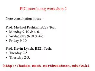
PIC interfacing workshop 2. Note consultation hours – Prof. Michael Peshkin, B227 Tech. Monday 9-10 & 4-6. Wednesday 9-10 & 4-6. Friday 9-10. Prof. Kevin Lynch, B221 Tech. Tuesday 2-5. Thursday 2-3. http://hades.mech.northwestern.edu/wiki. PIC 18F4520 – what can it do?.

E N D
PIC interfacing workshop 2 • Note consultation hours – • Prof. Michael Peshkin, B227 Tech. • Monday 9-10 & 4-6. • Wednesday 9-10 & 4-6. • Friday 9-10. • Prof. Kevin Lynch, B221 Tech. • Tuesday 2-5. • Thursday 2-3. http://hades.mech.northwestern.edu/wiki
PIC 18F4520 – what can it do? ~35 digital input lines (sensors) ~35 digital output lines (on/off) 8 analog inputs (ADC), 10-bit resolution 0 analog outputs! 2 PWM outputs (pulse width modulation, often for running motors) RS-232 serial communication I2C serial communication Interrupts 4 timers & counters
#include <18f4520.h> #DEVICE ADC=10 // set ADC to 10 bit accuracy #fuses HS,NOLVP,NOWDT,NOPROTECT #use delay(clock=20000000) int16 value; //f ro 10-bit res void main() { setup_adc_ports(AN0_TO_AN3); setup_adc(ADC_CLOCK_INTERNAL); while (TRUE) { set_adc_channel(0); delay_us(10); value = read_adc(); output_d(value>>2); if (value > 320) output_high(PIN_C0); else output_low(PIN_C0); delay_ms(10); } } Analog inputs; light measurements
Adjusting a variable value easily with a potentiometer set_adc_channel(0); delay_us(10); value = read_adc();
Digital inputs and outputs; magnetic sensing int onebyte, onebit; ... onebyte = input_c(); output_d(onebyte); onebit = input(PIN_C1);
Driving high current devices from a digital output Possible high-current device: a solenoid
Strobed light: more sensitivity less background light dependence set_adc_channel(0); delay_us(10); originalvalue = read_adc(); output_high(PIN_C0); // turn LED on delay_us(70); newvalue = read_ADC(); extralight = newvalue – oldvalue; Amplified phototransistor for strobed light
1. Motor + 2. +5V (or similar) to power the encoder3. Encoder channel A4. Encoder channel B5. GND for the encoder6. Motor -
Controlling RC servos 0.3mS < t < 2.5mS T ~ 20mS Servo’s rotor position depends on t Waveform can be generated by PIC software; see RCservoSoft.c
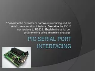
Serial output (“printf”) 2 line LCD uses RS232 code with a 0V/5V convention PC’s “comm port” uses RS232 code with a -7/+12V convention
#include <18f4520.h> #fuses HS,NOLVP,NOWDT,NOPROTECT #use delay(clock=20000000) // 20 MHz crystal on PCB #use rs232(baud=19200, UART1) // hardware UART; //uses RC6/TX and RC7/RX int16 i; int j; void main() { while (TRUE) { for (i=1; i<10000; i++) { printf("Hello world. %Lu %u\r\n", i, j); delay_ms(100); if (kbhit()) j = getc(); } } }
Analog Hall sensor (as opposed to digital Hall switch) 0-5V output depending on field (-1000 to +1000 gauss)