Download
1 / 19
190 likes | 312 Views
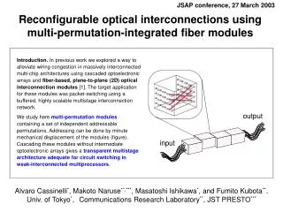
Two-dimensional fiber array with integrated topology for short-distance optical interconnections. Makoto Naruse 1),2) , Alvaro Cassinelli 3) , and Masatoshi Ishikawa 3) 1: Ultrafast Photonic Network Group Communications Research Laboratory , Japan E-mail: naruse@crl.go.jp

E N D
Two-dimensional fiber array with integrated topologyfor short-distance optical interconnections Makoto Naruse1),2), Alvaro Cassinelli3), and Masatoshi Ishikawa3) 1: Ultrafast Photonic Network Group Communications Research Laboratory , Japan E-mail: naruse@crl.go.jp 2: Japan Science and Technology Corporation (JST), PRESTO 3: Dept. Information Physics and Computing, University of Tokyo
Contents • Interconnection fabric • Wave-guide-base, direct implementation of interconnection topology • Interconnection decomposition • Experimental fabrication • Summary and future plans
Optical Interconnection fabric / switching fabric Optical interconnection Inter Chip, Inter-board Optical interconnection LSI LSI LSI LSI LSI LSI LSI LSI Optical Interconnection fabric / Switching fabric Multistage architecture
Input Output Multistage architecture Regularly interconnected multistage architecture An example: Omega network Optical interconnect Optoelectronic OE EO … Computation All optical Optical interconnect … w/o OEO
Wave-guide-base, direct implementation of interconnection topology Optoelectronic Optical interconnect OE EO … • Two-dimensional fiber array Computation All optical Optical interconnect Output … w/o OEO Input Configure the interconnection topology directly by positioning the input and output end of the wave-guides
Design considerations • Two-dimensional (2D) parallelism • Focus on Permutation network (such as perfect shuffle) • Scalability • Module reusability (Permutation reusability) Other remarks Out of scope of this paper • Alignment difficulty: Both input and output end • Theoretically more volume efficient than free-space equivalent Y.Li, et. al., “Volume-consumption comparisons of free-space and guided-wave optical interconnections”, Appl.Opt. 39 (2000), 1815
Input Output 0 1 2 3 4 5 6 7 8 9 10 11 12 13 14 15 Example1: Omega network • Messy topology • Poor scalability • Poor reusability 2D direct implementation Permutation=Perfect shuffle
Example 2:Indirect Binary n-Cube Network Several kinds of different interconnection topology are used Permutation=Butterflyandperfect shuffle
Interesting fact Perfect shuffle and butterfly permutation can be made out of the following three types of elemental permutations: Row, Column, and Diagonal permutations Row permutation Column permutation Diagonal permutation
0 1 2 3 4 5 6 7 8 9 10 11 12 13 14 15 Before decomposition Perfect shuffle 0 1 2 3 4 5 6 7 8 9 10 11 12 13 14 15 Direct implementation Node assignment: Scan mapping
14 2 1 6 Interconnection decomposition Perfect shuffle 0 1 2 3 4 5 6 7 8 9 10 11 12 13 14 15 0 1 2 3 4 5 6 7 8 9 10 11 12 13 14 15 Decompose Diagonal permutation Column permutation Row permutation
3 10 10 3 Interconnection decomposition Butterfly 0 1 2 3 4 5 6 7 8 9 10 11 12 13 14 15 0 1 2 3 4 5 6 7 8 9 10 11 12 13 14 15 Decompose Column permutation Diagonal permutation Column permutation
shuffle shuffle shuffle shuffle Processor arrays (exchange switches andmore) Overall Omega Network Row permutation 90º Column permutation Diagonal permutation
Processor arrays (exchange switches andmore) Overall Indirect Binary n-Cube Network (2) -1(4) (3) (4) Row permutation 90º Column permutation Diagonal permutation
Prototype fiber module: Preliminary 4x4 array 5 mm 3 mm 2 mm Two holder prototypes: Zirconium, SiO2 Pitch: 250±5m Multimode graded index fibers: NA=0.21 (core 50m, cladding 126m) Transmission loss: 3dB/km Length: 30 cm Embedded interconnection topology
Pitch uniformity Zirconium 16 245mm-255mm Ave. 250mm Std deviation 2.0mm SiO2 14 246mm-254mm Ave. 250mm Std deviation 1.5mm 12 10 Number of link 8 6 Pitch (250mm) 4 2 0 244 246 248 250 252 254 256 Pitch (mm)
Interconnection example Output (CCD image) Input Input Fiber module input VCSEL array Output No relay optics
Transmission efficiency / Alignment tolerance Transmission efficiency 0.25 45 0.2 40 38.45 x 0.15 Exit power (a.u) 35 LED regime LASER regime 0.1 30 25 0.05 Transmittance (%) 20 0 15 -105 -90 -75 -60 -45 -30 -15 0 15 30 45 60 75 10 X (microns) 5 Alignment tolerances 0 6 7 8 9 10 11 12 13 (half peak power) 9.5 VCSEL driving current (mA) x 50 m y 70 m Max. transmittance 38.45%
Summary and future plans • Wave-guide-base, direct implementation of 2D parallel interconnection topology • Interconnection decomposition for scalability and reusability • 2D fiber array with interconnection topology was demonstrated Future plan: • Theoretical foundation for interconnection decomposition and total system design • Higher-density 2D interconnect • System demonstration