Download
1 / 46
460 likes | 465 Views
EECS 373 Design of Microprocessor-Based Systems Prabal Dutta University of Michigan Serial buses. Some material from: Brehob, Le, Ramadas, Tikhonov & Mahal. This Week: Serial interfaces. traps & exceptions. C Assembly Machine Code. CPU. EECS 370. ldr (read) str (write). Software

E N D
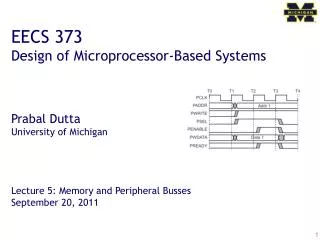
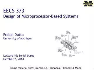
EECS 373 Design of Microprocessor-Based Systems Prabal Dutta University of Michigan Serial buses Some material from: Brehob, Le, Ramadas, Tikhonov & Mahal
This Week: Serial interfaces traps & exceptions C Assembly Machine Code CPU EECS 370 ldr (read) str (write) Software Hardware SVC# ISA fault INT# System Buses interrupts AHB/APB Interrupts GPIO/INT Internal & External Memory Timers USART DAC/ADC Internal External EMC SPI DAC I2C ADC Input UART Output Capture Compare Interrupt
Outline • Introduction to Serial Buses • UART • SPI • I2C
Serial bus interface motivations • Motivation • Connect different systems together • Two embedded systems • A desktop and an embedded system • Connect different chips together in the same embedded system • MCU to peripheral • MCU to MCU • Without using a lot of I/O lines • I/O lines require I/O pads which cost $$$ and size • I/O lines require PCB area which costs $$$ and size • Often at relatively low data rates • But sometimes at higher data rates • So, what are our options? • Universal Synchronous/Asynchronous Receiver Transmitter • Also known as USART (pronounced: “you-zart”)
Serial bus design space • Number of wires required? • Asynchronous or synchronous? • How fast can it transfer data? • Can it support more than two endpoints? • Can it support more than one master (i.e. txn initiator)? • How do we support flow control? • How does it handle errors/noise?
Fun with buses • A multidrop bus (MDB) is a computer bus in which all components are connected to the same set of electrical wires. (from Wikipedia) • In the general case, a bus may have more than one device capable of driving it. • That is, it may be a “multi-master” bus as discussed earlier.
How can we handle multiple (potential) bus drivers? (1/3) • Tri-state devices, just haveone device drive at a time. Everyone can read though • Pros: • Very common, fairly fast, pin-efficient. • Cons: • Tri-state devices can be slow. • Especially drive-to-tristate? • Need to be sure two folks not driving at the same time • Let out the magic smoke. • Most common solution (at least historically) • Ethernet, PCI, etc.
How can we handle multiple (potential) bus drivers? (2/3) • MUX • Just have each device generate its data, and have a MUX select. • That’s a LOT of pins. • Consider a 32-bit bus with 6 potential drivers. • Draw the figure. • How many pins needed for the MUX? • Not generally realistic for an “on-PCB” design as we’ll need an extra device (or a lot of pins on one device) • But reasonable on-chip • In fact AHB, APB do this.
How can we handle multiple (potential) bus drivers? (3/3) • “pull-up” aka “open collector” aka “wired OR” • Wire is pulled high by a resistor • If any device pulls the wire low, it goes low. • Pros: • If two devices both drive the bus, it still works! • Cons: • Rise-time is very slow. • Constant power drain. • Used in I2C, CAN
Outline • Introduction to Serial Buses • UART • SPI • I2C
UART • Universal Asynchronous Receiver/Transmitter • Hardware that translates between parallel and serial forms • Commonly used in conjunction with communication standards such as EIA, RS-232, RS-422 or RS-485 • The universal designation indicates that the data format and transmission speeds are configurable and that the actual electric signaling levels and methods (such as differential signaling etc.) typically are handled by a special driver circuit external to the UART. Most of the UART stuff (including images) Taken from Wikipedia!
Protocol • Each character is sent as • a logic lowstart bit • a configurable number of data bits (usually 7 or 8, sometimes 5) • an optional parity bit • one or more logic high stop bits • with a particular bit timing (“baud”) • Examples • “9600-N-8-1” <baudrate><parity><databits><stopbits> • “9600-8-N-1” <baudrate><databits><parity><stopbits>
Variations and fun times • UART is actually a generic term that includes a large number of different devices/standards. • RS-232 is a standard that specifies • “electrical characteristics and timing of signals, the meaning of signals, and the physical size and pin out of connectors.
Signals (only most common) • The RXD signal of a UART is the signal receiving the data. This will be an input and is usually connected to the TXD line of the downstream device. • The TXD signal of a UART is the signal transmitting the data. This will be an output and is usually connected to the RXD line of the downstream device. • The RTS# (Ready to Send) signal of a UART is used to indicate to the downstream device that the device is ready to receive data. This will be an output and is usually connected to the CTS# line of the downstream device. • The CTS# (Clear to Send) signal of a UART is used by the downstream device to identify that it is OK to transmit data to the upsteam device. This will be an input and is usually connected to the RTS# line of the upstream device.
DB9 stuff • DTE vs DCE • Pinout of a DCE? • Common ground? • Noise effects? Wiring a DTE device to a DCE device for communication is easy. The pins are a one-to-one connection, meaning all wires go from pin x to pin x. A straight through cable is commonly used for this application. In contrast, wiring two DTE devices together requires crossing the transmit and receive wires. This cable is known as a null modem or crossover cable.
Discussion Questions • How fast can we run a UART? • What are the limitations? • Why do we need start/stop bits? • How many data bits can be sent? • 9600-8-N-1 is ok. Is 9600-8192-N-1 ok too?
Outline • Introduction to Serial Buses • UART • SPI • I2C
Introduction • What is it? • Basic Serial Peripheral Interface (SPI) • Capabilities • Protocol • Pro / Cons and Competitor • Uses • Conclusion Serial Peripheral Interface http://upload.wikimedia.org/wikipedia/commons/thumb/e/ed/ SPI_single_slave.svg/350px-SPI_single_slave.svg.png
What is SPI? • Serial Bus protocol • Fast, Easy to use, Simple • Everyone supports it
SPI Basics • A communication protocol using 4 wires • Also known as a 4 wire bus • Used to communicate across small distances • Multiple Slaves, Single Master • Synchronized
Capabilities of SPI • Always Full Duplex • Communicating in two directions at the same time • Transmission need not be meaningful • Multiple Mbps transmission speed • Transfers data in 4 to 16 bit characters • Multiple slaves • Daisy-chaining possible
Protocol • Wires: • Master Out Slave In (MOSI) • Master In Slave Out (MISO) • System Clock (SCLK) • Slave Select 1…N • Master Set Slave Select low • Master Generates Clock • Shift registers shift in and out data
Wires in Detail • MOSI – Carries data out of Master to Slave • MISO – Carries data from Slave to Master • Both signals happen for every transmission • SS_BAR – Unique line to select a slave • SCLK – Master produced clock to synchronize data transfer
Shifting Protocol Master shifts out data to Slave, and shift in data from Slave http://upload.wikimedia.org/wikipedia/commons/thumb/b/bb/SPI_8-bit_circular_transfer.svg/400px-SPI_8-bit_circular_transfer.svg.png
Diagram Some wires have been renamed Master and multiple daisy-chained slaves http://www.maxim-ic.com/appnotes.cfm/an_pk/3947 Master and multiple independent slaves http://upload.wikimedia.org/wikipedia/commons/thumb/f/fc/SPI_three_slaves.svg/350px-SPI_three_slaves.svg.png
Clock Phase (Advanced) • Two phases and two polarities of clock • Four modes • Master and selected slave must be in same mode • Master must change polarity and phase to communicate with slaves of different numbers
Timing Diagram Timing Diagram – Showing Clock polarities and phases http://www.maxim-ic.com.cn/images/appnotes/3078/3078Fig02.gif
Pros and Cons Pros: • Fast and easy • Fast for point-to-point connections • Easily allows streaming/Constant data inflow • No addressing/Simple to implement • Everyone supports it Cons: • SS makes multiple slaves very complicated • No acknowledgement ability • No inherent arbitration • No flow control
Uses • Some Serial Encoders/Decoders, Converters, Serial LCDs, Sensors, etc. • Pre-SPI serial devices
Summary • SPI – 4 wire serial bus protocol • MOSI MISO SS SCLK wires • Full duplex • Multiple slaves, One master • Best for point-to-point streaming data • Easily Supported
Outline • Introduction to Serial Buses • UART • SPI • I2C
Exercise: How fast can I2C run? • How fast can you run it? • Assumptions • 0’s are driven • 1’s are “pulled up” • Some working figures • Rp = 10 kΩ • Ccap = 100 pF • VDD = 5 V • Vin_high = 3.5 V • Recall for RC circuit • Vcap(t) = VDD(1-e-t/τ) • Where τ = RC
Exercise: Bus bit rate vs Useful data rate • An I2C “transactions” involves the following bits • <S><A6:A0><R/W><A><D7:D0><A><F> • Which of these actually carries useful data? • <S><A6:A0><R/W><A><D7:D0><A><F> • So, if a bus runs at 400 kHz • What is the clock period? • What is the data throughput (i.e. data-bits/second)? • What is the bus “efficiency”?