Download
1 / 35
350 likes | 477 Views
EECS 373 Design of Microprocessor-Based Systems Prabal Dutta University of Michigan Lecture 10: Serial buses Oct 6, 2011. Announcements. Homework #1 Due now ABET procedure. Serial buses attach to the processor via the APB (which is bridged to the AHB). Atmel SAM3U. Outline.

E N D
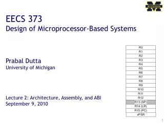
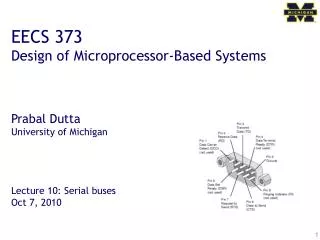
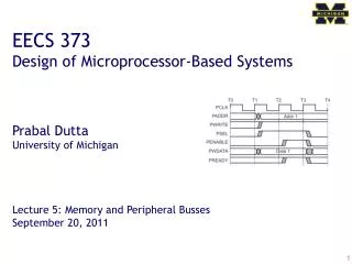
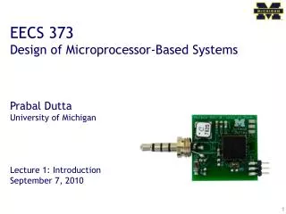
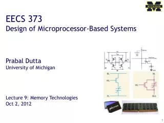
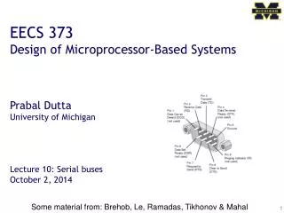
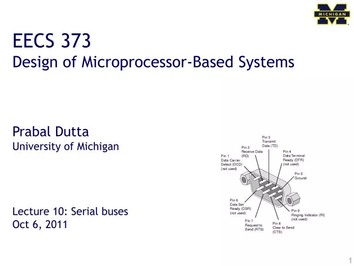
EECS 373 Design of Microprocessor-Based Systems Prabal Dutta University of Michigan Lecture 10: Serial buses Oct 6, 2011
Announcements • Homework #1 • Due now • ABET procedure
Serial buses attach to the processor via the APB (which is bridged to the AHB) Atmel SAM3U
Outline • Minute quiz • Announcements • UART • SPI • I2C
DB9 pinout of a DTE • DTE vs DCE • Pinout of a DCE? • Common ground? • Noise effects?
RS-232 transmission example How do peers agree on timing?
Outline • Minute quiz • Announcements • UART • SPI • I2C
Serial Peripheral Interface • What is it? • Basic SPI • Capabilities • Protocol • Pros and Cons • Uses Serial Peripheral Interface http://upload.wikimedia.org/wikipedia/commons/thumb/e/ed/ SPI_single_slave.svg/350px-SPI_single_slave.svg.png
What is SPI? • Serial bus protocol • Fast, easy to use, and simple • Very widely used • Not “standardized”
SPI Basics • A 4-wire communications bus • Typically communicate across short distances • Supports • Single master • Multiple slaves • Synchronized • Communications are “clocked”
SPI Capabilities • Always full-duplex • Communicates in both directions simultaneously • Transmitted (or received) data may not be meaningful • Multiple Mbps transmission speeds • 0-50 MHz clock speeds not uncommon • Transfer data in 4 to 16 bit characters • Supports multiple slaves
SPI bus wiring • Bus wires • Master-Out, Slave-In (MOSI) • Master-In, Slave-Out (MISO) • System Clock (SCLK) • Slave Select/Chip Select (SS1#, …, SS#n or CS1, …, CSn) • Master asserts slave/chip select line • Master generates clock signal • Shift registers shift data in and out
SPI signal functions • MOSI – carries data out of master to slave • MISO – carries data out of slave to master • Both MOSI and MISO are active during every transmission • SS# (or CS) – unique line to select each slave chip • SCLK – produced by master to synchronize transfers
SPI uses a “shift register” model of communications Master shifts out data to Slave, and shifts in data from Slave http://upload.wikimedia.org/wikipedia/commons/thumb/b/bb/SPI_8-bit_circular_transfer.svg/400px-SPI_8-bit_circular_transfer.svg.png
Two bus configuration models Some wires have been renamed Master and multiple daisy-chained slaves http://www.maxim-ic.com/appnotes.cfm/an_pk/3947 Master and multiple independent slaves http://upload.wikimedia.org/wikipedia/commons/thumb/f/fc/SPI_three_slaves.svg/350px-SPI_three_slaves.svg.png
SPI clocking: there is no “standard way” • Four clocking “modes” • Two phases • Two polarities • Master and selected slave must be in the same mode • During transfers with slaves A and B, Master must • Configure clock to Slave A’s clock mode • Select Slave A • Do transfer • Deselect Slave A • Configure clock to Slave B’s clock mode • Select Slave B • Do transfer • Deselect Slave B • Master reconfigures clock mode on-the-fly!
SPI timing diagram Timing Diagram – Showing Clock polarities and phases http://www.maxim-ic.com.cn/images/appnotes/3078/3078Fig02.gif
SPI tradeoffs: the pros and cons • Pros • Fast for point-to-point connections • Easily allows streaming/constant data inflow • No addressing in protocol, so it’s simple to implement • Broadly supported • Cons • Slave select/chip select makes multiple slaves more complex • No acknowledgement (can’t tell if clocking in garbage) • No inherent arbitration • No flow control (must know slave speed)
SPI is used everywhere! • Peripherals • LCDs • Sensors • Radios • Lots of other chips • Microcontrollers • Almost all MCUs have SPI masters • Some have SPI slaves
Outline • Minute quiz • Announcements • UART • SPI • I2C
I2C bus • Inter-Integrated Circuit • Pronounced “eye-squared-see” • Sometimes called “eye-two-see” • Two wire serial bus specification • Invented by Philips in the early 1980s • The division is now NXP • Was a patented protocol, but patent has now expired
I2C uses • Originally used by Philips inside television sets • Now a very common peripheral bus standard • Intended for use in embedded systems • Philips, National, Xicor, Siemens, … all use • Also used in PCs • RTC • Temperature sensors • Variant is the SMBus (system management bus)
I2C bus architecture • I2C • Standardizes peripheral classes • SCK, SDA • Philips/NXP
I2C details • Two-wire serial protocol with addressing capability • Speeds up to 3.4 Mbps • Discussion: what limits I2C to such small speeds? • Multi-master architecture • Open collector bus driver • Pull-up resistors • Multi-master, Multi-slave • Uses bus arbitration
I2C wiring • Two lines • SDA (serial data) • SCL (serial clock) • Open collector design • Simple interfacing in for multi-voltage • Supports bus arbitration
I2C clock • Not a “traditional” clock • Normally is kept “high” using a pull-up • Pulsed by the master during data transmission • Master could be either the transmitter or receiver • Slave device can hold clock low if needs more time • Allows for flow control
I2C transaction • Transmitter/receiver differs from master/slave • Master initiates transactions • Slave responds • Transmitter sets data on SDA line, slave acks • For a read, slave is transmitter • For a write, master is transmitter
I2C start condition • Master pulls SDA low while SCL is high • Normal SDA changes only happen when SCL is low
I2C address transmission • Data is always sampled on the rising clock edge • Address is 7 bits • An 8-th bit indicated read or write • High for read • Low for write • Addresses assigned by Philips/NXP • For a fee • Was covered by patent
I2C data transmission • Transmitted just like address (8 bits) • For a write, master transmits, slave acknowledges • For a read, slave transmits, master acknowledges • Transmission continues • Subsequent bytes sent • Continue until master creates stop condition
I2C stop condition • Master pulls SDA high while SCL is high • Also used to abort transactions
Questions? Comments? Discussion?