Download
1 / 34
340 likes | 342 Views
Learn about software engineering methods and processes, including modeling languages and tools, UML, and iterative development.

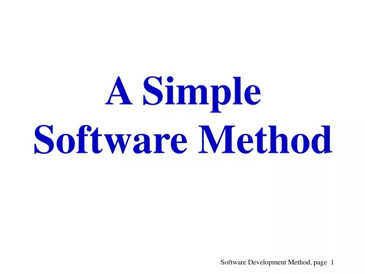
E N D
Software Engineering Methods • Most methods consist of both a modeling language and a process(who is doing what and when). • The modeling language, the notation, typically include some visual language (different types of diagrams). • A tool to support the method is also crucial.
UML Is Not a Process A “complete” development process defines: - Who is doing What, - When to do it, and - How to reach a certain goal • The UML is intentionally process independent, and defining a standard process was not a goal of UML. Different domain may require different processes. • But the UML authors promote a development process that is use-case-driven, architecture centric, iterative and incremental. (Example of method: RUP)
Software Development - Two Processes at the Same Time • The Management Process - schedules work, resources and deliveries, monitor progress. • The Development Process - develop software from requirements.
The Development Process is Subservient to the Management Process • Since the management process controls project, risk it has to be paramount. • Some methods contains both processes, e.g. RUP, others are mostly development processes, like Catalysis, and others again are management processes, e.g. Dynamic Systems Development Method (DSDM).
Analysis Purpose: understand the problem domain and the system to be implemented. Design Purpose: transform the products of the analysis phase into a more precise description that can be refined into an executable program. Implementation Purpose: transform the products of the design phase into concepts that can be executed on the computer (programming). Testing and Integration The waterfall model of software development Requirements Capture Purpose: communicate with end users and document the requirements. “Defining the right project”.
Requirements Capture • There are two types of requirements: functional and nonfunctional. • Functional requirements is often modeled with use cases. A use case is a short story describing a particular use of the system - a model of a dialogue between an actor and the system. The model can be visualized with a use case diagram! • Example of a nonfunctional requirement:“the data is stored on ASCII files”. • Sometimes the user interface is developed or a prototype of the system is made.
Analysis • The analysis includes object analysis and behavior analysis. • In object analysis all the key concepts related to the system are documented with the help of class diagrams. • In behavior analysis the system is model as a black box, only external functionality is modeled. A operation list is produced.
Design • Design deals with objects and functions that will be programmed. • The classes from the analysis phase is extended with operations. Classes necessary for the implementation are added. • The operations are modeled with sequence diagrams. From the sequence diagrams we can see the responsibility of the different classes and how the classes interact.
Static path Analysis Class Diagrams Design Class Diagrams Implmentation Declarations Requirements class X{ .... } ..... class X class X class Y use case 1 attribut1 .... attribut1 .... attribut1 .... Test Cases method() ... use case 1 Operation Lists use case 2 use case 2 Methods Sequence Diagrams operation 1 operation 2 .... void func1() {......} ...... obj1 Obj2 met1() Functional path
.... Requirements Analysis Design Implementation Testing Requirements .... First Cycle Iterative and incremental development. • Each cycle consist of one or more of the process components (requirement, analysis,...), typicallyonly a part (an increment) of the required functionality is implemented through each cycle. • At each cycle the requirements are verified and validated, this can lead to changed requirements. • In each cycle the most risky functionality is addressed, the cycle is aimed at eliminating the risk. In this way serious problems is exposed at an early stage, in some cases this can lead to termination of the project.
Types of risks • The requirements do not specify the right system. • The selected technology is not adequate for solving the given types of problems. • People with the right skills are not available to the project. • There are political forces that will try to stop or delay the project.
High-level view of the development phases • Inception - the vision of the project is specified. A go-ahead of the project is given. • Elaboration - the project is planned. Features and architecture is elaborated. • Construction - the system is developed through a series of iterations. • Transition - the product is set in production. User training is given. • In each phase the cycle of analysis, design, implementation and testing is preformed repeatedly.
The development process R = Requirements At each phase several complete cycles are possible. In the beginning requirements capture and analysis is focused, the other process components are more important later on. A = Analysis D = Design I = Implementation T = Testing Example of development process: R A R A R A D A D I D I T I T Inception Elaboration Construction Transition
Use Case Driven Object Modeling withUMLtm:A Practical Approach by Doug Rosenberg and Kendall Scott
Significant Features • Iterative and Incremental. • Traceability ~ you always refer back to the requirements. (Objects are there to satisify use cases.) • A ”minimalist” approach - a minimal number of steps and use of diagram types.
obj1 Obj2 Use Case Text met1() 1 User.. 2 … Cancel Boundary1 Entity1 Control1 Ok Sequence Diagram GUI Prototype Entity2 Control2 class A attribut1 .... class AA class AB attribut1 .... attribut1 .... Dynamic Use Case Model Robustness Diagram (Class Diagram) Static Design Class Diagrams Domain Model Class Diagrams
class A attribut1 .... class AA class AB attribut1 .... attribut1 .... Requirements Analysis • Domain Modeling • Identify your real-world domain objects and the generalization and aggregation relationships among those objects. • GUI design / Prototyping • If it’s feasible, do some rapid prototyping of the proposed system. (Mine your legacy software). ”…the best way to identify chunks of use cases in connection with a prototype is to write a rough user manual, as if the prototype were an actual fully working system.” • Use Case Modeling • Identify your use cases. • Organize the use cases into packages. • Allocate functional requirements to the use cases and domain objects at this stage. Cancel Ok
Boundary1 Entity1 Control1 Entity2 Control2 class A attribut1 .... class AA class AB attribut1 .... attribut1 .... Analysis And Preliminary Design --- 1 --- EndUser chooses Tourism/ Environment --- 2 --- EndUser chooses fishing --- 3 --- …… • Write Use Case Text • Write describtion of the normal flow (also called main flow, the ”sunny day” scenario) and the alternate flows (extensions) • Robustness Analysis. For Each Use Case: • Identify a first cut of objects that accomplich the selected scenario. • Update your domain model and your design class diagrams with new objects and attributes as you discover them.
obj1 Obj2 Use Case Text met1() 1 User.. 2 … Sequence Diagram Design • Interaction Modeling (Allocate behavior).For Each Use Case: • Identify the messages that need to be passed between objects, the objects, and the associated methods to be involved.Draw a sequence (or collobaration) diagram with use case text running down the left side.Continue to update the design class diagram with attributes and operations as you find them.
obj1 Obj2 met1() Boundary1 Entity1 Control1 Sequence Diagram Entity2 Control2 class A attribut1 .... class AA class AB attribut1 .... attribut1 .... Dynamic Use Case Model Robustness Diagram (Class Diagram) Static Design Class Diagrams Domain Model Class Diagrams
The use case model ~heartof the approach • Robustness analysis • What satisfy each use case? • Propose a set of collaborating objects that can solve each use case. • Interaction modeling • Refine the results of robustness analysis. • Show how messages flow between the collaborating objects that solves each use case. The use case model is pumping through the following modeling activities.
The Domain Modeling Is A Conceptual Model - Perspectives • Conceptual: The concepts of the problem domain are addressed. The class diagrams produced under the analysis will typically be of the conceptual type. The diagrams are not tied to any software implementation. • Specification: This perspective is closer to software. Interfaces is specified, but not the implementation. It is said that types are specified and not classes. This perspective is typically employed under design. • Implementation: The class diagrams produced will reflect the classes that is to be implemented.
Class Name attribute: Type = initialValue .... method(arg list): return type .... Class • An object has three characteristics: state, behavior and a unique identification. • A class is a template for instantiation of objects. A class diagram contains an attribute (state) and a method (behavior) section: • The level of and the numbers of details in the class diagram can vary, this depends on where you are in the development process. It is for example usual to leave the method section out under analyses.
Discover Classes • The high-level problem statement • Lower-level requirements • Expert knowledge of the problem space • Use cases if already present
Discover Classes Grammatical Inspection Noun: a word that names or denotes something.E.g.: Fisher doesn’t know which river to choose…. Nouns become objects Fisher River Noun Phrases:E.g.: Fisher selects a seasonal fishing license… Nouns Phrasesbecome attributes FishingLicense cardType:String
Operations and Associations Grammatical Inspection Verbs becomeoperations Verbs: E.g.:He uses the localisation service to find his object in the service. Locator getObject() Verb Phrases:E.g.: The user can use different devices … Verb Phrasesbecome associations uses EndUser Device
Attributes Rather Than Objects Possessive Phrases:E.g.: A fishing card has a limited duration.. Possessive Phrases indicate that nouns should be attributes rather than objects FishingCard duration
Robustness Diagram Symbols(Class Stereotypes) • Control Class: Manage interactions. Itsbehavioir is specific to a use case, which itusally does not outlive. • Boundary Class: Mediate between the system and outside actors (e.g. sensor). Often their lifeline coincide with the life of the system. • Entity Class: Passive objects, they do not initiate interactions. May participate several use cases.
Robustness Diagram Rules Allowed Not Allowed
Use Case ~ Robustness [1] ”…you’re not finished with a use case until the text and the robustness diagram match.”
References • Grady Booch, James Rumbaugh and Ivar Jacobson:The Unified Modeling Language User Guide.Addison-Wesley, 1999 • James Rumbaugh, Michael Blaha, William Premerlani, Frederick Eddy and William Lorenzen: Object-Oriented Modeling and Design. Prentice Hall, 1991 • Martin Fowler with Kendall Scott: UML Distilled.Addison-Wesley, 1997 • Terry Quatrani: Visual Modeling with Rational Rose and UML.Addison-Wesley, 1998 • Ari Jaaksi: A Method for Your First Object-Oriented Project. JOOP - The Journal of Object-Oriented Programming, Januar 1998 • Rational software: http://www.rational.com/uml/documentation.html • [1] Doug Rosenberg and Kendall Scott:Use Case Driven Object Modeling withUML:A Practical ApproachAddison-Wesley