Download
1 / 26
260 likes | 507 Views
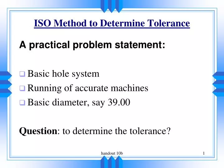
ISO Method to Determine Tolerance. A practical problem statement: Basic hole system Running of accurate machines Basic diameter, say 39.00 Question : to determine the tolerance?. ISO Method to Determine Tolerance. Issues: Basic size selection International Grade

E N D
ISO Method to Determine Tolerance A practical problem statement: • Basic hole system • Running of accurate machines • Basic diameter, say 39.00 Question: to determine the tolerance? handout 10b
ISO Method to Determine Tolerance Issues: • Basic size selection • International Grade • Determine the preferred fit • Determine tolerances handout 10b
Basic size (preferred) • Dimensions are initially determined by designers from a point of view of functions. • From the view point of function, the length of a bar may be like 39.6 • From a point of view of manufacturing, 39.6 is not a convenient figure, and therefore needs to be rounded up (say, 40) (see figure 1) handout 10b
Figure 1 handout 10b
International Grade Fundamental deviation (FD) Deviation closest to the basic size International Tolerance Grade (IT) FD can vary in an infinite number of possible numbers. In theory, the number of tolerances is infinite. To restrict such an infinite number of possible tolerances, we group FDs into groups and assign them by a grade. Small Deviation large Deviation IT0, IT1, IT2, .... IT16 handout 10b
Further, tolerance should be given such that large tolerance is given to large grade. Basic size group (1) With the same idea of IT grade, we group basic sizes into groups. The tolerance is only applied to the groups. (2) Large basic size gets large tolerance. handout 10b
Basic size IT 1 IT 5 0.0012 0.008 10-18 18-30 0.0015 0.009 Tolerance with respect to size group and IT group IT values are further associated with manufacturing processes (see Figure 2) handout 10b
Figure 2 handout 10b
Manufacturing process and technology Deviation (or tolerance) International Tolerance (IT) Grade Basic size Tolerance = f (FD, basic size, IT grade) handout 10b
50.005 50.030 G H k J h 50 49.05 • FD (block in the following diagram) is located with respect to basic size (in total there are 27 FDs) • Different location is given a name (letter) • Different location of FD finally comes up with tolerance handout 10b
H: a special location of FD, and this location makes the minimum diameter of the hole is the basic size of the hole, so the tolerance of the hole implies the basic hole system in the mind of designer handout 10b
Shaft h: a special location of FD, and this location makes the maximum diameter of the shaft is the basic size of the shaft, so the tolerance of the shaft implies the basic shaft system in the mind of designer handout 10b
Basic hole system with indication of three types of fits Basic shaft system with indication of three types of fits handout 10b
Figure 3 Complete set of FDs for hole and shaft handout 10b
Basic size Tolerance zone A combination of location of FD and IT grade 40 H7 handout 10b
ISO Method to Determine Tolerance Hole - minimum hole size as basic diameter - denoted by Capital letter (say, H) Basic size Fundamental Deviation 40 H8 IT grade Tolerance zone handout 10b
Shaft - maximum shaft size as basic diameter - denoted by small letters (say, h) Basic size Fundamental Deviation 40 h7 IT grade Tolerance zone handout 10b
Figure 4. Preferred fit handout 10b
ISO Method to Determine Tolerance Preferred fit: Product Function determines Fit. For instance, two parts need to have relative motion, so we require therefore clearance fit. handout 10b
Procedure to determine tolerance Re-visit the example: • Basic hole system • Running of accurate machines • Basic diameter, say 39 Step 1: go to Figure 1, the closed size to 39 is 40. Step 2: Go to Figure 4, H8/f7 handout 10b
Step 3: Go to Table 1a, we will find that under the size 40, and column H8 H8 f7 Fit 40.039 39.975 0.089 (max clearance) 40.000 39.950 0.025 (min clearance) handout 10b
Summary of the procedure The following figures and table are used: • Figure 1: Get a preferred size • Figure 4: Get a preferred fit • Table 1a: Get tolerance handout 10b
More Examples Given: basic hole system locational transitional fit basic diameter =57 mm Figure 1 -> 60 Figure 4 -> H7/k6 Table 1: Hole Shaft 60.030 60.021 60.000 60.002 handout 10b
Hole Shaft 60.030 60.021 60.000 60.002 • Tolerance • Tolerance -0.021 0.028 Max interference Max clearance 0.019 0.030 handout 10b
60.030 60.000 ) ( 60H7 60.021 60.002 ) ( 60k6 Representation on the drawing 60.021 60.002 handout 10b