Download
1 / 20
210 likes | 362 Views
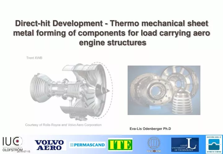
Direct-hit Development - Thermo mechanical sheet metal forming of components for load carrying aero engine structures. Eva-Lis Odenberger Ph.D. Flygteknik 2010. Project background.

E N D
Direct-hit Development - Thermo mechanical sheet metal forming of components for load carrying aero engine structures Eva-Lis Odenberger Ph.D
Flygteknik 2010 Project background • The European aero engine industry focus on alternative manufacturing methods for load carrying structures in titanium and nickel based super alloys • Traditionally consisting of large-scale single castings • Fabrication - involves sheet metal parts, small ingots and simple forgings assembled by welding - to decrease weight and thereby fuel consumption - to reduce product cost and increase the in-house level of processing
Flygteknik 2010 Project background • FE-technology is used to suggest and evaluate candidate hot forming procedures to perform a direct-hit development work at short lead times in which the costly die tryout can be kept at a minimum • Challenge is accurate prediction and compensation for springback and shape deviation which occur in the different steps of the manufacturing chain Courtesy of Volvo Aero Corporation and IDC in Olofström AB
Flygteknik 2010 Project and research targets • Project funding from VINNOVA – NFFP4, NFFP5 for SME, BFS and VAC • Create possibilities for IUC and the Swedish SMEs within the projects to develop into new sub suppliers of titanium and nickel based sheet metal parts for the aero engine industry - VAC • Research activities promotes the development and necessary technology steps at the SME • Propose competitive forming techniques for double-curved geometries in the Titanium alloy Ti-6Al-4V and the nickel based super alloy INCO718 • Perform material- and FE-modeling for simulation of thermo mechanical forming of Ti-6Al-4V Shape deviation [mm]
Flygteknik 2010 Project and research targets • Suggest competitive forming techniques for double-curved geometries in the alloy Ti-6Al-4V and INCO718 • Perform material and FE-modeling for simulation of cold and thermo mechanical sheet metal forming • Perform thermo mechanical material characterization – to obtain experimental reference data with high accuracy for the material model calibration • Compare predicted responses with experimental observations • Manufacturing of prototype tools to produce commercial geometries of current interest for the aero engine industry • Prototype tools are developed with production in mind
Flygteknik 2010 Titanium • Ti-6Al-4V, the most frequently used alloy for aero space applications • Two phase (α+β) alloy, imply a variety of microstructures and property combinations • Elastic and inelastic anisotropy, elastic degradation with plastic straining • Asymmetry in yielding between tension and compression • Sensitive to the Bauschinger effect • Strain rate sensitive • Low formability in room temperature, flow softening and stress relaxation at higher temperatures
Flygteknik 2010 Titanium • Sheet metal forming of Ti-6Al-4V • Springback is extensive upon forming thin sheets, scattering behavior cause difficulties • The literature states that Ti-alloys are often formed at elevated temperatures using multistage forming with intermediate annealing or a second hot sizing operation • Super plastic forming (SPF) for complex geometries • These are time consuming processes INITIAL HOT FORMING TESTS 20 °C 400 °C 700 °C 900 °C 1050 °C DIE (20°C) Illustration of shape deviation with the start temperature
Flygteknik 2010 Thermo mechanical sheet metal forming of Ti-6Al-4V • Studies to perform single stage forming in the medium temperature range with focus on short cycle times • Performed material characterization and FE-simulations with models suitable for the chosen temperature range <550°C, models with different level of complexity • Virtual tool development to keep the manual die tryout at a minimum • Two components are produced by hot forming to evaluate the applicability of chosen methods and models Sheet metal parts (i) Ingot (ii) Metal deposition (iii) Prototype geometry (1) Courtecy of Volvo Aero Corporation Prototype geometry (2)
Flygteknik 2010 Thermo mechanical sheet metal forming of Ti-6Al-4V • A rather straight forward approach was applied for early evaluations of the first prototype component (1). The anisotropic yield criterion, [Barlat et al. (2003) with six coefficients] YLD2000 in LS-Dyna v971, was compared with an isotropic assumption at 400°C Tool setup
Flygteknik 2010 Thermo mechanical sheet metal forming of Ti-6Al-4V • For the second prototype component (2) the material characterization was extended to include uniaxial compression tests, Viscous bulge test and FLC tests to study forming limits • The anisotropic yield criteria [Cazacu et al. (2006), Barlat et al. (2003)] was compared with an isotropic assumption at 400°C Cazacu et al. (2006), a = 2 Barlat et al. (2003), m = 8
Flygteknik 2010 Thermo mechanical sheet metal forming of Ti-6Al-4V • Measured and predicted shape deviation [mm], Prototype component (1) Barlat et al. (2003)
Flygteknik 2010 Thermo mechanical sheet metal forming of Ti-6Al-4V • Measured and predicted shape deviation [mm], Prototype component (1) Isotropic assumption
Flygteknik 2010 Thermo mechanical sheet metal forming of Ti-6Al-4V • Measured and predicted shape deviation [mm], including the effect of cooling, Prototype component (2) Cazacu et al. (2006)
Flygteknik 2010 Thermo mechanical sheet metal forming of Ti-6Al-4V • Prediction of strain localization Cazacu et al. (2006) Isotropic assumption
Flygteknik 2010 On-going activities • Include anisotropy in coupled thermo mechanical FE-analyses up to 700°C • The temperature/time is important process parameters – minimize blank size • Thermo mechanical material characterization and inverse modeling for evaluation of material tests using the ARAMISTM systemand induction heating Tensile test specimen
Flygteknik 2010 Sheet metal forming of INCO718 Component (B) • Generate high quality prototype components at a short lead time by direct hit development work – 15 weeks • A systematic methodology for the design, compensation and manufacturing of five (5) different geometries • CAE-controlled process, manual die tryout kept at a minimum. Virtual components within tolerance • Evaluate the manufacturing process, compare predicted and measured values
Die Punch Drawbeads Blank holder Component Flygteknik 2010 Sheet metal forming of INCO718 The methodology comprises • material characterization • tool design and material selection • FE-analyses • springback compensation • tool manufacturing • choice of lubricant • prototype stamping • laser cutting • laser scanning, shape deviation & materialthinning determination. General tool-setup Deep drawing/stretch forming Tool concepts are secured and optimized with respect to • sheet metal formability • strain distribution & material thinning • reduce shape deviation, compensate tool surfaces using the FE-code LS-DYNA
Component (B) Sheet metal forming of INCO718 Test stamping – predicted and measured shape deviation (A) Predicted, section of component (A) Measured, section of component • Minor shape deviation, within tolerance, of component (A). • Normalized with respect to the sheet thickness - a value of 1.0 imply a shape deviation equal to the sheet thickness.
Component (B) Sheet metal forming of INCO718 Test stamping – predicted and measured shape deviation (B) Predicted, section of component (B) Measured, section of component • A small over-compensation of the tool geometry for component (B). Maximum shape deviation in the order of the sheet thickness, acceptable. • 2010 – IUC delivered a commercial INCO718 geometry to Volvo Aero Corporation (Airbus A380)
Flygteknik 2010 Thank you for your attention! Eva-Lis Odenberger Ph.D Industrial Development Centre in Olofström AB/OSAS Address Vällaregatan 30, SE-293 38 Olofström Phone 0454–975 00 I Fax 0454-921 21 I Direct 0454–975 45 I Mobile 0768-99 75 45 E-mail Eva-Lis.Odenberger@iuc-olofstrom.se I Webwww.iuc-olofstrom.se, www.osas.se References: Odenberger, E-L, Concepts for hot sheet metal forming of titanium, (2009), Doctoral Thesis, Luleå University of Technology. Odenberger E-L, Jansson M, Thilderkvist P, Gustavsson H, Oldenburg M, A short lead time methodology for design, compensation and manufacturing of deep drawing tools for Inconel 718, IDDRG2008 Conference Best in Class Stamping, Olofström.