Download
1 / 17
170 likes | 297 Views
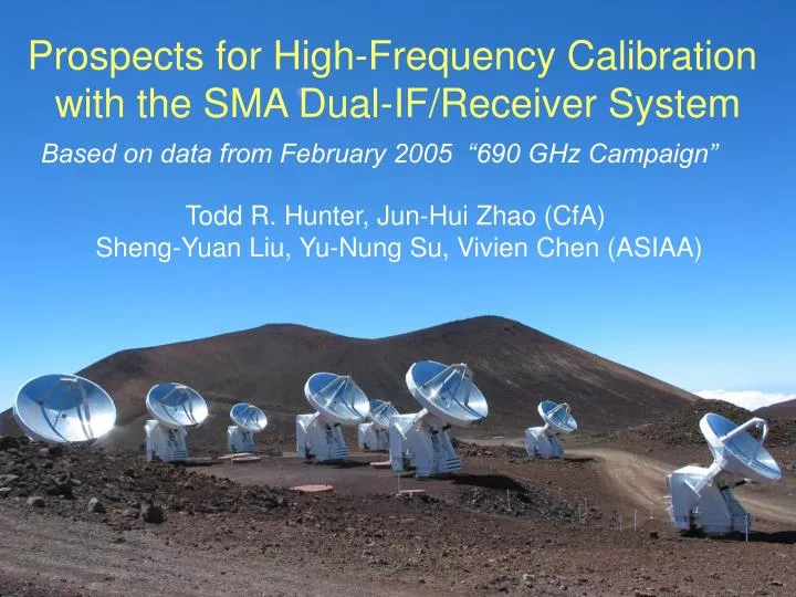
Prospects for High-Frequency Calibration with the SMA Dual-IF/Receiver System. Based on data from February 2005 “690 GHz Campaign”. Todd R. Hunter, Jun-Hui Zhao (CfA) Sheng-Yuan Liu, Yu-Nung Su, Vivien Chen (ASIAA). Lack of Strong Gain Calibrators.

E N D
Prospects for High-Frequency Calibration with the SMA Dual-IF/Receiver System Based on data from February 2005 “690 GHz Campaign” Todd R. Hunter, Jun-Hui Zhao (CfA) Sheng-Yuan Liu, Yu-Nung Su, Vivien Chen (ASIAA)
Lack of Strong Gain Calibrators SMA sensitivity: Tsys ~ 100 K at 230 GHz (10 mJy in 5 min) Tsys ~ 2500 K at 690 GHz (250 mJy in 5 min) For good phase solutions, we need S/N ~ 10 per baseline { 0.5 Jy at 230 GHz (70 quasars with F > 1Jy) 10 Jy at 690 GHz (maybe 1 or 2 quasars) This requires Quasars are inadequate for the SMA at 690GHz
Minor planets as calibrators Flux density Typical 230 GHz690 GHzDiameter Callisto 6 Jy 45 Jy 1.3” Ganymede 6 44 1.5” Ceres 2.6 14 0.5” Titan 1.1 9 0.7” Pallas 0.6 5 0.3” synthesized beam in compact configuration 1.1” • These objects work adequately if one of them is available • Otherwise, need lower frequency “phase transfer” with the SMA dual-IF system
Fundamental components of SMA dual-IF system 1. Common reference frequency LO 1 YIG, DDS 10 MHz LO 2 Receiver Feed 1 230 GHz Receiver Feed 2 690 GHz 2. Co-aligned receiver feeds ( < 1/6 beam) Correlator 2 IF 2 3. Duplicate paths for simultaneous down-conversion and correlator processing Correlator 1 IF 1 Antenna
January 28, 2005: First dual-IF fringes Simultaneous maser lines from W Hydra SiO J=5-4, v=1 at 215 GHz H2O 11,0-10,1 v=1 at 658 GHz These screens show only 2% of the total correlator data product.
First Dual-IF Phase vs. Time solutions 215 GHz maser in LSB 658 GHz maser in USB Ant 1 Ant 1 Ant 3 Ant 3 360o 360o About 3x larger phase change and opposite sign (as expected) 2 hours
Investigation of “Phase transfer”Part I: Observation strategy Observe four sources: 1. Strong, compact source (e.g. Ceres) to compare 230 and 690 phases 2. Stronger source (possibly resolved) for passband information (e.g. Callisto, Ganymede) 3. Science target 4. Quasar near the science target We had 7 nights with low opacity during the recent 690 GHz Campaign in February
Linear fit of Ceres 690 phase vs 230 phase Antenna Correlation Slope 1 0.97 3.0 2 0.85 2.3 3 0.95 2.4 4 0.88 2.3 5 0.94 3.2 6 reference antenna theory 1.00 3.0 USB data Antenna Correlation Slope 1 0.94 3.1 2 0.72 2.0 3 0.85 2.0 4 0.83 2.2 5 0.85 3.3 6 reference antenna theory 1.00 3.1 LSB data
Investigation of “Phase transfer”Part II. Search for phase relationships • Do passband calibration of calibrator and target • 2. Do phase-only selfcal on calibrator at 230 & 690 • 3. Examine correlations of 690 vs 230 phase solutions • 4. Flag any phase jumps or unstable periods that degrade the correlation • 5. Compute slope and offset relating 230 and 690 phases on each antenna
Example #0: phase transfer using Ceres (on itself) Ceres 230 Selfcal Ceres 690 Selfcal (rms = 50 mJy, S/N = 260) Derive coefficients and 690 gain table + Ceres phase transfer image Ceres 690 uncalibrated data Apply 690 gain table (rms = 70 mJy, S/N = 193)
Investigation of “Phase transfer”Part III: Imaging tests • Selfcal the test target at 230 GHz • Apply slope & offset from the phase transfer calibrator to create a new gain table appropriate for 690 GHz • 2. Image the test target at 690 GHz using the new gain table • 3. Compare with image from “normal” calibration
Example #1: phase transfer on a point source Quasar 1743-038 230 GHz selfcal solution Direct 690 GHz calibration (S/N=8) Apply coefficients from Ceres to make 690 gain table 690 GHz uncalibrated data 690 GHz phase transfer (S/N=5) Apply 690 gain table
Example #2: phase transfer on IRAS 16293-2422 The phase transfer analyses in the previous slides were done in Miriad. Here is an example done in MIR / IDL (see poster 4.69 by Su & Liu). In this case, the frequency ratio (rather than the fit) was used in the scaling. Direct 690GHz calibration (Ceres) Phase transfer from quasar 1743-038
Summary of 690 GHz calibration schemes in the “compact” configuration (1” to 5”)
Q: What limits this method?A: instrument problems 230GHz • Phase jumps and drift 90o jump Sometimes seen in one IF only, sometimes both. Under investigation. Also, slow changes in phase offset with time between the two IFs may require frequent measurement of phase transfer coefficients. 217 GHz 2. Phase vs. temperature We see 60 degrees of phase change at 690 GHz per oC of antenna cabin temperature change. Sensitive to any thermal imbalance between the IFs. No jump 679 GHz
Other limitations for 690 GHz calibration • 1. Passband measurements in extended configs • No point sources (< 0.4”) bright enough • Can we use Lunar limb? (works for measuring delays) • Noise source for passband phases? • Autocorrelation on the ambient load for amplitudes? • 2. Weather? • So far, best dual-freq. phase correlations occur on nights with little wind (< 10 mph, January 28), or constant wind direction (February 18, March 02) . Coincidence? More experience may tell us.
Summary and future work • We have demonstrated our first attempt at phase transfer at submm frequencies • Improvements are possible: • Cabin temperature control(antenna 6 now < 0.1 oC RMS) Phase jump investigation (and elimination) • New receiver band coming (320-420 GHz) • Will allow more frequent dual-band observations (due to less stringent weather requirements) and higher S/N testing of the phase transfer technique. Conclusion: We remain open-minded and hopeful to realize the full potential of the SMA.