Download
1 / 11
110 likes | 191 Views
Multi-level Simulation of a Real Time Vibration Monitoring System Component Bryan Robertson/EI31 NASA/Marshall Space Flight Center. Health Management System Overview RTVMS Design Overview Simulation Environment Summary.

E N D
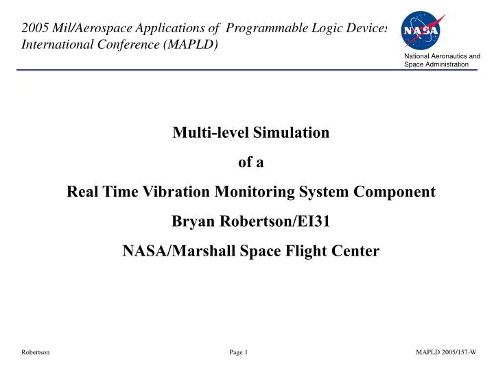
Multi-level Simulation of a Real Time Vibration Monitoring System Component Bryan Robertson/EI31 NASA/Marshall Space Flight Center
Health Management System Overview • RTVMS Design Overview • Simulation Environment • Summary
The advanced Real-Time Vibration Monitoring System (RTVMS) was developed as a component of the Space Shuttle Main Engine Advanced Health Management System. The RTVMS algorithm requires parallel DSP operation and provides real-time vibration analysis and health monitoring capabilities during engine operation by producing vibration spectral data from critical SSME Components. The RTVMS processing boards are designed to operate within the Health Management Computer Integrated Rack Assembly (HMC-IRA) during Main Engine Controller test activity at Stennis Space Center.
Real Time Vibration Monitoring System (RTVMS) Overview • First ED13 Multiple/Parallel Processing Digital Signal Processor (DSP) Design. • 5 Texas Instruments 320C40HFHM50 DSPs, each with 512K x 32 (2Mbytes) of SRAM on Local and Global Bus, 32K x 32 EEPROM, 8K x 32 DPSR, VME access as Master and Slave • First design to use System level simulations • Design was required to have a path to flight. • Designed with commercial version of flight quality components. EEE parts evaluation performed on selected flight components. • Timing constrained to those of flight components. • Challenging Printed Circuit Board Design • First 16 layer board. Previous ED16 designed board had max 14 layers. • Most densely populated board routed by ED16. 1012 components for baseboard, greater than 1800 total. 1.5 to 2 times more components than any previous ED16 design. • 28mil Via sizes utilized for the first time (previous size was 40mil). • First time Breakaway extensions for manufacturing utilized. • Developed PCB procurement standards now being used by other projects
MSFC Network XPLORER MS-3X00 ModelSource XPLORER MS-3X00 ModelSource Elements of Simulation Environment – Synopsys Hardware Model • Built by Synopsys using actual chips and interfaced to Hardware Modeler • - Actual silicon communicates with simulators • - Much faster than software models • - Elementary software code can be executed on microprocessors • Design and Simulation Tools reside on individual office computers Hardware Model Operation in B222 Lab Designer’s Office TMS320C40 DSP PC Interface to Hardware Models Designer’s Office HDL Simulator Fiber Optic Link Ethernet Link Designer’s Office
Mentor Graphics Design Capture Environment • Where the Elements of Design are “connected” together CASE addr IS WHEN "01000" => flash <= '0'; WHEN "01001" => flash <= '1'; WHEN "01010" => mps_pwr <= '1'; WHEN "01011" => mps_pwr <= '0'; WHEN "01100" => eng_pwr <= '1'; WHEN "01101" => eng_pwr <= '0'; WHEN "01110" => x_tvc_en <= '0'; WHEN "01111" => x_tvc_en <= '1'; Hardware Modeler Symbols VHDL Over 14,000 Fully Functional Models -- Memories -- Standard MSI/LSI Logic -- Bus functional microprocessors/DSP -- Bus functional microcontrollers -- Bus Interfaces (VME, PCI) -- Memories can be loaded with software to allow full board level simulation Software Model Library Symbols Licensed VHDL Software Model Representation Of a Gate Level Component with adjustable parameters
ModelSim Simulation Environment VHDL Simulation Hardware Modelers Schematic Capture Over 14,000 Fully Functional Models -- Memories -- Standard MSI/LSI Logic -- Bus functional microprocessors/DSP -- Bus functional microcontrollers -- Bus Interfaces (VME, PCI) -- Memories can be loaded with software to allow full board level simulation CASE addr IS WHEN "01000" => flash <= '0'; WHEN "01001" => flash <= '1'; WHEN "01010" => mps_pwr <= '1'; WHEN "01011" => mps_pwr <= '0'; WHEN "01100" => eng_pwr <= '1'; WHEN "01101" => eng_pwr <= '0'; WHEN "01110" => x_tvc_en <= '0'; WHEN "01111" => x_tvc_en <= '1'; HDL Software Model Library
RTVMS Component Level Verification • Functional Simulations were initially utilized to verify the Hardware Model and its surrounding logic. The simulations included.. • Ability to boot correctly from EEPROMs • 512k x 32 SRAM Access(Global and Local) • The timing of the simulation could be manipulated the following two ways: • TMS320C40 Hardware Model timing attribute • Synopsys Logic Memory Models timing attribute • Various simulations were run where the timing attributes were modified to simulate multiple conditions.
RTVMS Board Level and FPGA Verification • Once the Hardware Model and its surrounding logic were verified, the simulations were expanded to include RTVMS Board and FPGA verification. The simulations included.. • MGBC FPGA Register Access • MGBC FPGA Watchdog Operation • Dual-Port SRAM Access with arbitration inside the MGBC FPGA • DSP to DSP Comport Operations • Once the functionality was verified, the FPGA code was synthesized and the simulations repeated multiple times. The timing of the simulation could be manipulated in three ways in the: • TMS320C40 Hardware Model timing attribute • Synopsys Logic Memory Models timing attribute • Synthesized FPGA logic delays (min,typ,max)
HMC-IRA System Level Verification • The system level verification consisted of the following components to simulate multiple boards in a VME chassis: • 2 RTVMS Board Designs(Master and Slave) • 1 EADIF-A Board Design(Slave) • 1 VME Hardware Verification Logic Model(Master,Slave,System Controller) • PCL code was written for the VME Hardware Verification Model to operate as a System Controller • Functional and Timing simulations were executed to verify the following: • RTVMS VME Accesses(Single, Block, and Read-Modify-Write) of the System Controller • Execution of VME Interrupts • On-board VME Arbitration • VME Access of the RTMVS DPSR by the System Controller(RTVMS as a Slave) • EADIF-A to RTVMS DSP Comport Operation
Summary • The HMC-IRA RTVMS boards have completed all board level and system level verification tests and are waiting for delivery to the Stennis Space Center. • During testing no design errors with the 15 Engineering Unit and Brassboard were encountered. • Only slight modifications to the design was made between the Engineering Unit and Brassboard Unit boards. These changes were for routing purposes. The Engineering Unit boards met all requirements , re-spin of board would not have been required • Because of the detailed simulations and schedule time allocated for performing the simulations, no functional or timing errors have occurred. • Only one printed circuit board assembly had a manufacturing issue. Only one significant component failure with an UTMC SRAM.