Download
1 / 13
130 likes | 257 Views
Annealing of TID Effects of SMART sLHC Prototype SSD and Test Structures. H. F.-W. Sadrozinski, C. Betancourt, R. Heffern, I. Henderson, J. Pixley, A. Polyakov, M. Wilder SCIPP, UC Santa Cruz M. Boscardin, C. Piemonte, A. Pozza, S. Ronchin, N. Zorzi ITC-irst G.-F. Dalla Betta

E N D
Annealing of TID Effects of SMART sLHC Prototype SSD and Test Structures H. F.-W. Sadrozinski, C. Betancourt, R. Heffern, I. Henderson, J. Pixley, A. Polyakov, M. Wilder SCIPP, UC Santa Cruz M. Boscardin, C. Piemonte, A. Pozza, S. Ronchin, N. Zorzi ITC-irst G.-F. Dalla Betta DIT, Università di Trento M. Bruzzi Dipt. Energetica, Univ. of Florence A. Macchiolo INFN Florence L. Borello, A. Messineo INFN Pisa Donato Creanza, Noman Manna INFN Bari 9th RD50 Workshop Hartmut F.-W. Sadrozinski SCIPP-UC Santa Cruz
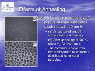
Motivation Many investigations of irradiated detectors concentrate on the charge collection from the bulk.. But detectors performance depends on parameters influenced by the surface condition: interstrip capacitance (noise), interstrip resistance (strip isolation), breakdown (high voltage operation after bulk damage), Irradiation with gamma‘s are probing the detector surface Treatment of surface very different for p-type and n-type detectors For p-type, p-spray dose varies widely, influencing the strip isolation and breakdown Expect effects in Si-SiO2 interface to saturate at the 100 kRad level (at this level very little effects in the bulk expected) Status of the stable surface very interesting for long-term operation TID effects are known to exhibit large annealing effects, which establishes the stable surface condition. 9th RD50 Workshop Hartmut F.-W. Sadrozinski SCIPP-UC Santa Cruz
Structures Investigated 9th RD50 Workshop Hartmut F.-W. Sadrozinski SCIPP-UC Santa Cruz
Wafers Investigated 9th RD50 Workshop Hartmut F.-W. Sadrozinski SCIPP-UC Santa Cruz
SSD Investigated 9th RD50 Workshop Hartmut F.-W. Sadrozinski SCIPP-UC Santa Cruz
Device Preparation Hi Lo TS: one strip vs. next neighbor pair un-bonded and unbiased except 3 following neighbor pairs bonded to bias (shield). Mini-SSD one strip vs. 3 next neighbor pairs 3 following neighbor pairs bonded to bias (shield). T.S. Pre-rad: Large difference shield bonded and un-bonded T.S. Post-rad: No difference shield bonded and un-bonded Ratio between mini-SSD and T.S. =1.2 (3 pairs vs. 1 pair) 9th RD50 Workshop Hartmut F.-W. Sadrozinski SCIPP-UC Santa Cruz
Irradiation and Annealing Gamma irradiation in the UCSC 60Co source 3.15 kRad/hr Irradiate in steps of one day (~70 kRad) and re-measure, with a few days to weeks in-between steps After TID of ~ 500 - 700 kRad, start 3 annealing steps: 1 week room temperature 1 week accelerated anneal at 60oC 1 week accelerated anneal at 60oC Re-measure after every step 2nd week of 60oC does not change the values: stable state is reached. Saturation and Annealing behavior consistent between structures and wafers Saturation and Annealing behavior very different for different parameters 9th RD50 Workshop Hartmut F.-W. Sadrozinski SCIPP-UC Santa Cruz
FBV = 3V Qox = 1*1011 FBV = 65 V Qox = 1*1012 MOS Cap Doping Density Nd, Flatband Voltage FBV, Oxide Charge Qox 9th RD50 Workshop Hartmut F.-W. Sadrozinski SCIPP-UC Santa Cruz
7 d RT 7 d RT 7 d RT 7 d 60oC 7 d 60oC 7 d 60oC 7 d 60oC 7 d 60oC 7 d 60oC Oxide Charge vs. Dose and Anneal Steps: Saturation before 150 kRad (p-only), Annealing to 1/3 of saturation value 9th RD50 Workshop Hartmut F.-W. Sadrozinski SCIPP-UC Santa Cruz
Breakdown Voltage Large TID effect on breakdown voltage considerable annealing ?Annealing of breakdown voltage leads to value independent of wafer type and p-spray? 9th RD50 Workshop Hartmut F.-W. Sadrozinski SCIPP-UC Santa Cruz
Cint vs. Dose and Annealing for T.S. Large TID effect on bias voltage dependence of interstrip capacitance of all p-type TS Saturation at 70 kRad No or very little annealing In n-type, large TID effect on bias voltage dependence of interstrip capacitance Saturation at 70 kRad No or very little annealing 9th RD50 Workshop Hartmut F.-W. Sadrozinski SCIPP-UC Santa Cruz
Cint pre-rad after saturation and anneal(4.45 cm mini-SSD, 100 mm pitch) Cint decreases rapidly with TID for p-type SSD high p-spray dose, slower decrease up to 600 kRad Wafers 14 and 37 are FZ, wafers 66 and 182 MCz. Little difference between different wafers, large dependence on the p-spray. Geometrical value is reached at moderate voltage after TID irradiation. The amount of annealing is limited. 9th RD50 Workshop Hartmut F.-W. Sadrozinski SCIPP-UC Santa Cruz
Conclusions The performance of p-type SSD with p-spray isolation can be improved with gamma irradiation of modest dose. (We are now pre-irradiating the high p-spray dose SSD to be irradiated with neutrons at Louvain.). MCz and FZ behave similar TID behavior Large dependence on p-spray dose. Saturation of effects, but at different dose for different parameters Large annealing in Qox and breakdown voltage, but not in Cint different types of TID surface damage ? 9th RD50 Workshop Hartmut F.-W. Sadrozinski SCIPP-UC Santa Cruz