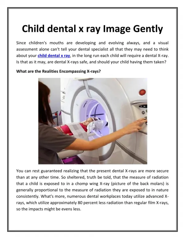
Download
1 / 29
340 likes | 944 Views
Invisible X-ray image. Formation Characteristics. X-ray tube. Plot of incident x-ray beam intensity. Object. Plot of transmitted x-ray beam intensity. Invisible x-ray image. Invisible x-ray image. kV mA Sec FFD. E. Supporting tissue (m). B. B1. T3. B2. T1. T2. Air.

E N D
Invisible X-ray image Formation Characteristics
X-ray tube Plot of incident x-ray beam intensity Object Plot of transmitted x-ray beam intensity Invisible x-ray image
Invisible x-ray image kV mA Sec FFD E Supporting tissue (m) B B1 T3 B2 T1 T2 Air Invisible X-ray image consists of different x-ray intensities E B1 E B2 ET1 EM EM ET2 ET3 EA
Characteristics • Subject contrast • Sharpness • Noise • Resolution
Subject contrast • The difference in the x-ray intensities transmitted through the subject • It is the shortened form of the radiation contrast of the subject Causes of subject contrast • Differential attenuation • Scattered radiation
Differential attenuation • Differential attenuation is the result of the attenuation caused by Photoelectric absorption and Compton scattering. • Depends on • Thickness of the anatomical structure • Effective atomic number of the body tissues • Physical density of the body tissues • Presence of radiological contrast medium • X-ray tube kilovoltage employed • X-ray beam filtration
Effective atomic number & Subject contrast • For a given Photon energy the photo electric absorption is higher when the atomic number is high ( bone absorbs more radiation than soft tissue) • E.g. if the three tissues A,B,C have effective atomic numbers as Z1 > Z2 > Z3 Incident intensity A Z1 B Z2 C Z3 Subject contrast A-B Transmitted intensity Subject contrast A-C Subject contrast B-C
X-ray tube kilovoltage & subject contrast • Photo electric absorption predominates at low kilovoltages, therefore at low kilovoltages the subject contrast is high, and when the kilovoltage is increased the subject contrast tend to be reduced. • At high kilovoltages approaching 150kV the contrast is mainly caused by the compton effect which mainly depends on the density difference of the anatomical structures.
kV & subject contrast Low kV E Supporting tissue (m) B B1 T3 B2 T1 T2 Air E B1 E B2 Higher differences ET1 EM EM ET2 ET3 EA
kV & subject contrast High kV E Supporting tissue (m) B B2 B1 T3 T1 T2 Air Lower differences E B1 E B2 EM EM ET1 ET2 ET3 EA
X-ray beam filtration & Subject contrast • Filtration reduces the low energy components of the x-ray beam. Hence increasing the filtration has the effect of increasing the effective photon energy of the beam. This influences the photoelectric absorption in a similar way as increasing the tube kilovoltage. • Therefore increasing the filtration will decrease the subject contrast
Scattered radiation & subject contrast Scattered radiation Primary beam
Scattered radiation & subject contrast • When the primary beam from x-ray tube interacts with matter scattered radiation is produced. • Scattered radiation travels in different paths from the primary beam and will reduce the subject contrast of the invisible x-ray image. • Not only the subject contrast but it will reduce the signal to noise ratio also.
Scatter reduces the subject contrast E Supporting tissue (m) B B2 B1 T3 T1 T2 Air Scatter Lowers the differences E B1 E B2 EM EM ET1 ET2 ET3 EA
How to minimize the effect of scatter on subject contrast? • Reduce the amount of scatter produced at the object (patient) by: • Collimating the primary beam • Reducing the proportion of forward scatter using low kV • Reducing the tissue thickness • Avoiding other sources of scatter, such as bucky tray • Protecting the image receptor by • Use of secondary radiation grid • Employing an air gap
Use of grid Lead strips Image receptor Radiolucent inter-space
Employing Air gap Image plane 2 Image plane 1 Object Scatter Air gap Percentage of oblique ray reaching the image receptor plane is reduced at image plane 2
Sharpness of Invisible x-ray image • The sharpness is determined first by the geometry of image formation • The size of the source of radiation is of primary concerned • Infinite size (Point source) • Finite size ( larger than a point) • When the size of the x-ray source (Focus) is large the sharpness of the image is less
Image Geometry Finite source Point source Image plane Unsharpness (penumbra)
Intensity distribution at previous situations Intensity of x-rays at image plane Intensity of x-rays at image plane U U Distance across image plane Distance across image plane
Geometric unsharpness • The formation of unsharpness due to a penumbra is a direct consequence of the finite size of the x-ray source. • This form of unsharpness is known as Geometric unsharpness (UG) • It can be shown that focal spot size x object-image distance Geometric = ------------------------------------------- Unsharpness focus-object distance
Evaluation of Geometric unsharpness Source A B Triangles OAB & OCD are similar. AB/CD = OB/OC Re-arranging CD = AB x OC/OB UG = focal size x OFD/FOB Object O Image plane C D
Factors governing geometric unsharpness • Focal spot size • Small focus gives minimum geometric unsharpness • Object image (film) distance • Shorter OFD gives less geometric unsharpness • Focus to object ( Focal film) distance • Longer the FFD lesser the geometric unsharpness • Increase the FFD when OFD cannot be reduced, to minimize the geometric unsharpness • Edge penetration
Focal spot size & Geometric unsharpness • Unsharpness increases, when apparent focal area increases • Apparent (effective) focal area = Actual focal area x Sine of target angle • Therefore Unsharpness increases when target angle increases for a given actual focal spot size • Geometric Unsharpness can be reduced by using small focus but that reduces the maximum tube loading capacity
This is due to the shape of the object The edges of the object absorb less amount of radiation and the absorption increases towards the centre This creates a intensity gradient producing inherent unsharpness Unsharpness due to Edge penetration Intensity of x-rays at image plane Distance across image plane
Movement unsharpness • Voluntary & involuntary movement of the organs or body parts or the patient as a whole will cause changes in the pattern of x-ray intensities forming the invisible x-ray image • This changes are referred to as movement unshrpness : UM • If they occur during image recording they will produce unsharpness in the final image
Noise in the invisible x-ray image • The kinds of noise present in the invisible x-ray image are • Fog due to scatter radiation • Quantum noise – presence of less number of photons in the invisible x-ray image, making the identification of gaps between individual photons and finally making the recorded image looks grainy. • Quantum noise can be avoided by using adequate exposure factors producing high enough x-ray intensity
Resolution of invisible x-ray image • The resolution depends on • contrast, • sharpness and • noise. • We must try to obtain maximum resolution at this stage because the resolution becomes less and less in the next stages of image production
Conclusion • It is important to know the details of production and characteristics of the invisible x-ray image because; • If the invisible x-ray image is of poor quality, it is extremely difficult to produce an adequate standard of final visible image. • It is during the production of the invisible x-ray image that the radiographer has the greatest scope for control of image quality, particularly in conventional radiography.