Download
1 / 46
480 likes | 868 Views
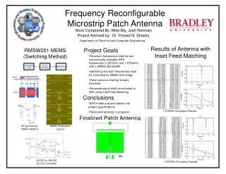
Frequency Reconfigurable Microstrip Patch Antenna. Final Project Presentation. Presented by: Mike Bly, Josh Rohman Advisor: Dr. Prasad N. Shastry. Why Reconfigurable Antennas? Practical Applications?. Presentation Outline. Design Specifications MEMS Switch Implementation

E N D
Frequency Reconfigurable Microstrip Patch Antenna Final Project Presentation Presented by: Mike Bly, Josh RohmanAdvisor: Dr. Prasad N. Shastry
Presentation Outline • Design Specifications • MEMS Switch Implementation • Linear Patch Antenna Design • Antenna Simulations • Inset Feed Matching Network
Design Specifications • Microstrip patch antenna (Rogers RO3010) • 2 GPS application frequencies • 24 MHz Bandwidth • 1.575 GHz Center Frequency (Patch 1) • 1.227 GHz Center Frequency (Patch 2) • Linear Polarization • Inset Feed matching network • Matched to 50Ω • MEMS preferred for switching method
Switching Method • MEMS Switch • RMSW201, RADANT MEMS • 0.3dB Insertion Loss @ 2GHz • 35dB Isolation Loss @ 2GHz • 1.9mm x 1.85mm package size
RMSW201 MEMS Operation • +/- 90 VGS Actuation Voltage
RMSW201 MEMS Operation +/- 90 VGS Actuation Voltage
Implementing MEMS • RS = RD = 100kΩ • Stability
Switching Method • DC-DC Converter: +5V to -90V • R2/R1 = Vout/Vref • R2 = Vout/10uA +5VDC -90VDC
Switching Method DC-DC Converter: +5V to -90V +5VDC -90VDC
Switching Method DC-DC Converter: +5V to -90V +5VDC -90VDC
Switching Method DC-DC Converter: +5V to -90V +5VDC -90VDC
Implementing MEMS • Conductive epoxy, double-stick thermal tape • Wire bonding, gold plating
Micro-Circuits, Inc. • Contact: Robert Modica • (630) 628-5764 • microcir@aol.com
Patch Antenna Design Step 1 ΔL = 0.412h*[(εeff + 0.3)(W/h + 0.264)]/[( εeff – 0.258)(W/h + 0.8)] W = c/(2fo*√((εr+1)/2)) L = c/(2fo*√(εr)) – 2ΔL L = 30mm & W = 40.25mm L = 38.6mm & W = 40.25mm
Patch Antenna Design Step 2 <-Height = 1mm L = 30mm & W = 40.25mm
Patch Antenna Design Step 3 Height = 1.9mm Height = 1mm L1 = 30mm & W = 40.25mm
Simulations: 1.575 GHz Patch Antenna • 1 to 2 GHz Simulation
Simulations: 1.227 GHz Patch Antenna • 1 to 2 GHz Simulation
Inset Feed Design Step 1 y0 = [Cos-1(Z0/Zin)]2*(L/π) W0 = 0.6mm (50Ω microstrip line) W1 = W0
Inset Feed Design Step 2 Height = 1mm L = 30mm & W = 40.25mm & y0 = 10.25mm
Sources: • Application Note for MAX774 DC-to-DC Converter. RadantMEMS, 2007. Web. Nov. 2011. <http://www.radantmems.com/radantmems.data/Library/MAX774%20DC-DC%20Converter_1.2.pdf>. • Application Note for Test & Handling of SPST RF-MEMS Switches. RadantMEMS, 2007. Web. Nov. 2011. <http://www.radantmems.com/radantmems.data/Library/App_notes_1.6.pdf>. • Balanis, Constantine A. Antenna Theory: Analysis and Design. 3rd ed. Hoboken, NJ: John Wiley, 2005. Print. • DeSignor, Jessica A., and Jayanti Venkataraman. "Reconfigurable Dual Frequency Microstrip Patch Antenna Using RF MEMS Switches." IEEE Xplore. May 2007. Web. 20 Sept. 2011. • Rebeiz, Gabriel M., and Jeremy B. Muldavin. "RF MEMS Switches and Switch Circuits." IEEE Xplore. Dec. 2001. Web. 20 Sept. 2011. • SPST, High-Isolation, RF-MEMS Switch DC to 20 GHz. RadantMEMS, 2007. Web. 28 Oct. 2011. <http://www.radantmems.com/radantmems.data/Library/Radant-Datasheet201_1.4.pdf>. • Yang, Songnan, Chunna Zhang, Helen K. Pan, Aly E. Fathy, and Vijay K. Nair. "Frequency Reconfigurable Antennas for Multiradio Wireless Platforms." IEEE Microwave Magazine (2009): 67-84. Print.