Download
1 / 45
450 likes | 618 Views
18: Ethernet, Hubs, Bridges, Switches. Last Modified: 11/29/2014 6:52:06 AM. Ethernet. “dominant” LAN technology: First widely used LAN technology Kept up with speed race: 10, 100, 1000 Mbps. Metcalfe’s Ethernet sketch. Ethernet Frame Structure.

E N D
18: Ethernet, Hubs, Bridges, Switches Last Modified: 11/29/2014 6:52:06 AM 5: DataLink Layer
Ethernet “dominant” LAN technology: • First widely used LAN technology • Kept up with speed race: 10, 100, 1000 Mbps Metcalfe’s Ethernet sketch 5: DataLink Layer
Ethernet Frame Structure Sending adapter encapsulates IP datagram (or other network layer protocol packet) in Ethernet frame Preamble: • 7 bytes with pattern 10101010 followed by one byte with pattern 10101011 • used to synchronize receiver, sender clock rates 5: DataLink Layer
Ethernet Frame Structure (more) • Addresses: 6 bytes, frame is received by all adapters on a LAN and dropped if address does not match • Type: indicates the higher layer protocol, mostly IP but others may be supported such as Novell IPX and AppleTalk) • CRC: checked at receiver, if error is detected, the frame is simply dropped 5: DataLink Layer
Ethernet: Unreliable, connectionless • connectionless: No handshaking between sending and receiving NICs • unreliable: receiving NIC doesn’t send acks or nacks to sending NIC • stream of datagrams passed to network layer can have gaps (missing datagrams) • gaps will be filled if app is using TCP • otherwise, app will see gaps • Ethernet’s MAC protocol: unslotted CSMA/CD Data Link Layer
Ethernet: uses CSMA/CD A: sense channel, if idle then { transmit and monitor the channel; If detect another transmission then { abort and send jam signal; update # collisions; delay as required by exponential backoff algorithm; goto A } else {done with the frame; set collisions to zero} } else {wait until ongoing transmission is over and goto A} 5: DataLink Layer
Ethernet’s CSMA/CD (more) Jam Signal: make sure all other transmitters are aware of collision; 48 bits; Exponential Backoff: • Goal: adapt retransmission attempts to estimated current load • heavy load: random wait will be longer • first collision: choose K from {0,1}; delay is K x 512 bit transmission times • after second collision: choose K from {0,1,2,3}… • after ten or more collisions, choose K from {0,1,2,3,4,…,1023} 5: DataLink Layer
Manchester encoding • used in 10BaseT • each bit has a transition • allows clocks in sending and receiving nodes to synchronize to each other • no need for a centralized, global clock among nodes! • Hey, this is physical-layer stuff! Data Link Layer
Ethernet Technologies: 10Base2 • 10: 10Mbps; 2: under 200 meters max cable length • thin coaxial cable in a bus topology • repeaters used to connect up to multiple segments • repeater repeats bits it hears on one interface to its other interfaces: physical layer device only! 5: DataLink Layer
10BaseT and 100BaseT • 10/100 Mbps rate; latter called “fast ethernet” • T stands for Twisted Pair • Hub to which nodes are connected by twisted pair, thus “star topology” • CSMA/CD implemented at hub 5: DataLink Layer
10BaseT and 100BaseT (more) • Max distance from node to Hub is 100 meters • Hub can disconnect “jabbering adapter” • Hub can gather monitoring information, statistics for display to LAN administrators 5: DataLink Layer
Gbit Ethernet • use standard Ethernet frame format • allows for point-to-point links and shared broadcast channels • in shared mode, CSMA/CD is used; short distances between nodes to be efficient • uses hubs, called here “Buffered Distributors” • Full-Duplex at 1 Gbps for point-to-point links 5: DataLink Layer
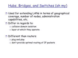
Repeaters • Physical Layer devices: operating at bit levels: repeat received bits on one interface to all other interfaces • Extend the range of a signal by amplifying • Useful when want to connect devices beyond the IEEE 802.3 specifications for distance limitation of 328 feet or 100 meters • Examples – outdoor installations, mine shafts, remote locations, etc. 5: DataLink Layer
Hubs • Also physical layer device, but may have some management • Hubs can be arranged in a hierarchy (or multi-tier design), with backbone hub at its top • Hubs do not isolate collision domains: node may collide with any node residing at any segment in LAN • Hub Advantages: • Simple, inexpensive device • Multi-tier provides graceful degradation: portions of the LAN continue to operate if one hub malfunctions • Extends maximum distance between node pairs (100m per Hub) 5: DataLink Layer
twisted pair hub Hubs … physical-layer (“dumb”) repeaters: • bits coming in one link go out all other links at same rate • all nodes connected to hub can collide with one another • no frame buffering • no CSMA/CD at hub: host NICs detect collisions Data Link Layer
Hub limitations • Single collision domain results in no increase in max throughput • multi-tier throughput same as single segment throughput • Also less secure – hear traffic from/to everyone on the hub • Individual LAN restrictions pose limits on number of nodes in same collision domain and on total allowed geographical coverage • Difficult to connect different Ethernet types, but can have dual speed hubs (e.g., 10BaseT and 100baseT) 5: DataLink Layer
Switch • link-layer device: smarter than hubs, take active role • store, forward Ethernet frames • examine incoming frame’s MAC address, selectively forward frame to one-or-more outgoing links when frame is to be forwarded on segment, uses CSMA/CD to access segment • transparent • hosts are unaware of presence of switches • plug-and-play, self-learning • switches do not need to be configured Data Link Layer
Switch: allows multiple simultaneous transmissions A • Switch isolates collision domains • Hosts have dedicated, direct connection to switch • A-to-A’ and B-to-B’ simultaneously, without collisions • not possible with dumb hub • Does not forward out all interfaces • Buffers frames • Ethernet protocol used on each incoming link, but no collisions; full duplex • each link is its own collision domain C’ B 1 2 3 6 4 5 C B’ A’ switch with six interfaces (1,2,3,4,5,6) Data Link Layer
Collision domain • When I speak, who else can I prevent from speaking at the same time • Hub = one collision domain; Switch = collision domain per port • Broadcast domain • When I deliberately send a broadcast address, who all hears it • VLANs separate broadcast domains 5: DataLink Layer
Managed vs Unmanaged • Switches more likely than hubs or repeaters to have sophisticated management features • Log in remotely and configure, get reports/statistics etc. • More control over what each port or group of ports can do (e.g. establish groups of ports into virtual LANs or VLANs that further divide the broadcast domain) 5: DataLink Layer
Switches (more) • Switch advantages: • Isolates collision domains resulting in higher total max throughput and more security • Can connect different type Ethernet since it is a store and forward device ( dual speed hub is compromise between full switch and hub that does this) 5: DataLink Layer
Switch: frame filtering, forwarding • Switches filter packets • same-LAN -segment frames not forwarded onto other LAN segments • Forwarding: • how to know which LAN segment on which to forward frame? • looks like a routing problem? 5: DataLink Layer
Source: A Dest: A’ MAC addr interface TTL 60 1 A A A’ Switch: self-learning A • switchlearns which hosts can be reached through which interfaces • when frame received, switch “learns” location of sender: incoming LAN segment • records sender/location pair in switch table C’ B 1 2 3 6 4 5 C B’ A’ Switch table (initially empty) Data Link Layer
Switch: frame filtering/forwarding When frame received: 1. record link associated with sending host 2. index switch table using MAC dest address 3. ifentry found for destinationthen { ifdest on segment from which frame arrivedthen drop the frame else forward the frame on interface indicated } else flood forward on all but the interface on which the frame arrived Data Link Layer
Source: A Dest: A’ A’ A MAC addr interface TTL 60 60 1 4 A A’ A A’ A A’ A A’ A A’ A A’ A A’ Self-learning, forwarding: example A • frame destination unknown: C’ B 1 2 3 flood 6 4 5 • destination A location known: C selective send B’ A’ Switch table (initially empty) Data Link Layer
Generally on a switch only see traffic to/from your machine and broadcast traffic • Can attack switch by sending many MACs and overflowing its storage of which MACs on which port => will begin to act like hub ( flooding each packet out every port) 5: DataLink Layer
S4 S3 S2 F I D H G E Interconnecting switches • switches can be connected together S1 A C B • Q: sending from A to G - how does S1 know to forward frame destined to F via S4 and S3? • A: self learning! (works exactly the same as in single-switch case!) Data Link Layer
network link physical link physical datagram datagram frame frame frame Switches vs. Routers application transport network link physical • both store-and-forward devices • routers: Layer 3 or network-layer devices (examine network-layer headers) • switches are Layer 2 or link-layer devices (examine link-layer headers) • routers maintain routing tables, implement routing algorithms • switches maintain switch tables, implement filtering, learning algorithms switch application transport network link physical Data Link Layer
Switch Pros and Cons + Switch operation is simpler requiring less processing bandwidth - Topologies are restricted with bridges: a spanning tree must be built to avoid cycles - Switch do not offer protection from broadcast storms (endless broadcasting by a host will be forwarded by a bridge) 5: DataLink Layer
Routers Pros and Cons + arbitrary topologies can be supported, cycling is limited by TTL counters (and good routing protocols) + provide firewall protection against broadcast storms - require IP address configuration (not plug and play) - require higher processing bandwidth 5: DataLink Layer
Network Diagrams Shared 5: DataLink Layer
Sample Icons • Icons for in network diagrams 5: DataLink Layer
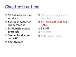
Summary • Layer 3 Devices (Network Layer) • Router • Layer 2 Devices (Link Layer) • Bridge • Switch • Layer 1 Devices (Physical Layer) • Repeaters • Hubs 5: DataLink Layer
Outtakes 5: DataLink Layer
Institutional network mail server to external network web server router IP subnet Data Link Layer
Switch Learning: example Suppose C sends frame to D and D replies back with frame to C • C sends frame, switch has no info about D, so floods to both LANs • switch notes that C is on port 1 • frame ignored on upper LAN • frame received by D 5: DataLink Layer
Switch Learning: example • D generates reply to C, sends • switch sees frame from D • switch notes that D is on interface 2 • switch knows C on interface 1, so selectively forwards frame out via interface 1 5: DataLink Layer
Disabled Spanning Tree • for increased reliability, desirable to have redundant, alternate paths from source to dest • with multiple simultaneous paths, cycles result - bridges may multiply and forward frame forever • solution: organize bridges in a spanning tree by disabling subset of interfaces 5: DataLink Layer
Spanning Tree Algorithm 5: DataLink Layer
VLAN tagging 5: DataLink Layer
Interconnection Without Backbone • Not recommended for two reasons: - single point of failure at Computer Science hub - all traffic between EE and SE must path over CS segment 5: DataLink Layer
Backbone Switch 5: DataLink Layer
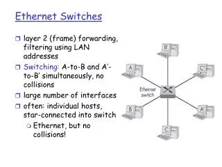
Ethernet Switches • Sophisticated bridges • Switches usually switch in hardware, bridges in software • large number of interfaces • Like bridges, layer 2 (frame) forwarding, filtering using LAN addresses • Can support combinations of shared/dedicated, 10/100/1000 Mbps interfaces 5: DataLink Layer
Switching • Switching: A-to-B and A’-to-B’ simultaneously, no collisions • cut-through switching: frame forwarded from input to output port without awaiting for assembly of entire frame • slight reduction in latency • Store and forward switching: entire frame received before transmission out an output port • Fragment-free switching: compromise, before send out the output port receive enough of the packet to do some error checking (ex. detect and drop partial frames) 5: DataLink Layer
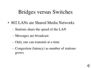
Ethernet Limitations Q: Why not just one big Ethernet? • Limited amount of supportable traffic: on single LAN, all stations must share bandwidth • limited length: 802.3 specifies maximum cable length • large “collision domain” (can collide with many stations) 5: DataLink Layer