Download
1 / 52
520 likes | 669 Views
THEMIS Mission Confirmation Readiness Feb 4 2004. AGENDA. 8:30 Introduction F. Snow, GSFC 8:40 Science Overview V. Angelopolous,UCB 9:00 Mission Overview P. Harvey, UCB 9:40 Probe & Probe Carrier M. Cully, Swales 10:00 SMO Assessment M. Goans, SRO 10:30 RAO Cost Estimate C. Fryer, SMO

E N D
THEMIS Mission Confirmation Readiness • Feb 4 2004
AGENDA 8:30 Introduction F. Snow, GSFC 8:40 Science Overview V. Angelopolous,UCB 9:00 Mission Overview P. Harvey, UCB 9:40 Probe & Probe Carrier M. Cully, Swales 10:00 SMO Assessment M. Goans, SRO 10:30 RAO Cost Estimate C. Fryer, SMO 11:00 Discussion GPMC
THEMIS Science Overview • Dr. Vassilis Angelopolous • Principal Investigator • Space Sciences Laboratory • University of California, Berkeley
TIME HISTORY OF EVENTS AND MACROSCALE INTERACTIONS DURING SUBSTORMS (THEMIS) • SCIENCE GOALS: • Primary: • “How do substorms operate?” • One of the oldest and most important questions in Geophysics • A turning point in our understanding of the dynamic magnetosphere • First bonus science: • “What accelerates storm-time ‘killer’ electrons?” • A significant contribution to space weather science • Second bonus science: • “What controls efficiency of solar wind – magnetosphere coupling?” • Provides global context of Solar Wind – Magnetosphere interaction RESOLVING THE PHYSICS OF ONSET AND EVOLUTION OF SUBSTORMS Principal Investigator Vassilis Angelopoulos, UCB EPO Lead Nahide Craig, UCB Program Manager Peter Harvey, UCB Industrial Partner SWALES Aerospace
Science Overview THEMIS determines where and how substorms are triggered. …important to NASA: Substorms are… • SEC Roadmap: “Understand energy, mass and flux transport in Geospace” • SEC Roadmap: “How does solar variability affect society?” • NRC, National Academy: A strategic question in space physics (1995). • Fundamental mode of magnetospheric circulation • Important for geo-storms have societal implications. • Rich in new types of basic space plasma physics. Aurora Current disruption Reconnection • Magnetospheric substorms are responsible for auroral eruptions. • Auroral eruptions are recurrent (~3-6hrs)
? Reconnection AuroralEruption CurrentDisruption Events Occuring During a Substorm
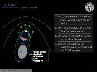
: Ground Based Observatory Mission Elements Probe conjunctions along Sun-Earth line recur once per 4 days over North America. … while THEMIS’s space-based probes determine onset of Current Disruption and Reconnection each within <10s. Ground based observatories completely cover North American sector; can determine auroral breakup within 1-5s …
Science Objectives • THEMIS HAS FOCUSED MINIMUM (TO BASELINE) OBJECTIVES: • Time History of Events… • Auroral breakup (on the ground) • Current Disruption [CD] (2 probes at ~10RE) • Reconnection [Rx] (2 probes at ~20-30RE) • … and Macroscale Interactions during >5 (>10) Substorms (Primary): • Current Disruption and Reconnection coupling • Outward motion (1600km/s) of rarefaction wave • Inward motion of flows (1000km/s) and Poynting flux. • Ionospheric coupling • Cross-tail current reduction (P5u/P4) vs flows • Field aligned current generation by flow vorticity, pressure gradients (dP/dz, dP/dx). • Cross-scale coupling to local modes • Field line resonances (10RE, 5 min) • Ballooning modes, KH waves (1RE, 1min) • Weibel instability, cross-field current instability, kinetic Alfven waves (0.1RE, 6Hz) • Production of storm time MeV electrons (Secondary) • Control of solar wind-magnetosphere coupling by the bow-shock, magnetosheath and magnetopause (Tertiary)
Probe conjunctions well understood • BASELINE: >10 substorms achieved w/ 5 probes in 2 yrs & 50% margin. • MINIMUM: >5 substorms achieved in 1yr w/ 4 probes. • computations include lunar, solar, drag, J2 terms • dYP1/2/3/4/5<±2RE; dZP3,4,5/NS<±2RE; dZP1,2/NS<±5RE • Ascent design is optimal for science • maximizes conjunctions, minimizes shadows • … immune to launch insertion errors • small, piece-wise DVs increase placement fidelity • … and immune to probe insertion errors. • Can withstand insertion error of dV=80cm/s on any probe Actual conjunction times in 1st year
EFIs EFIa SCM ESA BGS SST Operations UCB FGM Tspin=3s Instrument I&T UCB Ground Mission overview: Fault-tolerant design hasconstellation and instrument redundancy D2925-10 @ CCAS Encapsulation & launch Mission I&T Swales Probe instruments: ESA: Thermal plasmaSST: Super-thermal plasmaFGM: Low frequency B-fieldSCM: High frequency B-field EFI: Low and high frequency E-field
Selected instruments built en masse Identical instrumentation provides high science margins and fault tolerance • Instrument redundancy: • SST-ESA energy overlap • FGM-SCM frequency overlap • P1/P2 redundant instrumentation (only directional flux needed in one of two). • Each probe has: • FGM • ESA • 2SSTh (2heads) • SCM • 2EFIa (2axials) • 4EFIs (4spin plane)
First bonus: What producesstorm-time “killer” MeV electrons? Affect satellites and humans in space ANIK telecommunicationsatellites lost for days to weeksduring space storm • Source: • Radially inward diffusion? • Wave acceleration at radiation belt? • THEMIS: • Tracks radial motion of electrons • Measures source and diffusion • Frequent crossings • Measures E, B waves locally
Second bonus: What controls efficiencyof solar wind – magnetosphere coupling? • Important for solar wind energy transfer in Geospace • Need to determine how: • Localized pristine solar wind features… • …interact with magnetosphere • THEMIS: • Alignments track evolution of solar wind • Inner probes determine entry type/size
Mission design meets requirements • Mission profile • Two year mission design easily met in this high Earth orbit • Launch: D2925 from CCAS (40min window any day) • Simple probe carrier (3rd stage fixture) w/ release built by an experienced team • Science & routine ops and multi-object tracking has ample heritage at UCB • Simple RCS, heritage sfw & ground-cmd and GSFC/GNCD support benefits MOC • Probe design • Simple, passive thermal design w/ thermostatically controlled backup heaters • Survival at all attitudes under worst shadow conditions • Simple data flow / automated routine science ops minimize cost and risk • Store/Forward 375Mbit/orbit (256Mbyte capability permits multi-orbit storage) • Orbit control & knowledge exceed placement rqmts by factor of 10 • Early EMC/ESC mitigation as per heritage practices (e.g. FAST, POLAR)
Active trade studies constantly reduce risk An integrated team of scientists and engineers constantly optimize mission design and resources, reducing risk. • Phase A main trade studies: • Direct inject with passive PCA reduces schedule and ops risks • PCA dispense simplified: improves clearances, reduces risk • Increased fuel tank capacity • Added solar panels at bottom face • ACS solution simplified with micro-gyros replacing accelerometers • Connected RCS propulsion pods • Phase B main trade studies: • Exercised alternate path for SST instrument • Tuned Phase A orbit design to reduce differential precession; enhanced 2nd year science products • Changed BAU processor to reduce software complexity motivated by GSFC experience • Increased tank size to take full advantage of mass to orbit capability, yet at lower cost • Increased thruster size to reduce finite arc inefficiency and Msn Ops complexity • Repackaged SST and SCM electronics along with IDPU • Removed ESA attenuator (simplified instrument) with minimal effect on bonus science • Included redundant actuators and surge protection in instrument designs
Descope list and science-relatedrisk mitigation factors • Can do baseline science even after inadvertent complete instrument failures • Re-positioning allows recovery from failure of critical instruments on some probes • Graceful degradation results from partial or even full instrument failures • Instrument frequency and energy range overlaps • Complete backup option for EFI radials (need 2 in most probes but have 4) • Relaxed measurement requirements (1nT absolute is not permitted to drive team, but rather a nicety) • Substorms come in wide variety; can still see large ones with degraded instruments • Minimum mission can be accomplished with a reduced set of spacecraft requirements • EMC and ESC requirements important for baseline but less severe for minimum mission • Observation strategy can be tuned to power loss (turn-on/off) and thermal constraints (tip-over/back) • Fuel and mass margins for 1st year (minimum) are 30% larger than for a two year (baseline) mission
P1 P2 P3 P4 P5 Minimum mission provides definitive answer to the substorm question. • Simultaneous observations in the key regions • Ideal geometries for tens of substorms • Data rates / time resolution exceed requirements • Analysis tools available from Cluster, ISTP, FAST • Experienced co-Is are leaderson both sides of substorm controversy • Minimum mission accomplished within 8 months from nominal launch date
THEMIS Mission Overview • Peter R. Harvey • Project Manager • Space Sciences Laboratory • University of California, Berkeley
Salient Features • Science • Purpose To understand the onset and macroscale (1-10 Re) evolution of magnetospheric substorms. • Capabilities Will provide the first measurements of substorm starting location Will provide the first measurements of substorm evolution • Collaborating Institutions
Salient Features • Mission Parameters • Launch Vehicle: Delta II, Eastern Range Injection: 1.1 x 12 Re, 9 degrees inclination Date: August 2006 ( unrestricted ) • Space Segment Spacecraft: 5 Spinning probes with fuel for orbit/attitude adjust Orbit Period(s): 1, 2 and 4 days Orientation: Ecliptic normal • Ground Segment Observatories: 20 Stations for All Sky Imaging and Mag Field • Operations Phases: L&EO (2 mo), Campaigns (Dec-Mar), De-Orbit Lifetime: 2 years
Launch Configuration Standard Delta 10 ft. Fairing Static Envelope • Dedicated launch accommodated within standard Delta 7925-10 vehicle configuration and services • 10’ Composite Fairing required to accommodate five Probes on the Probe Carrier in the “Wedding Cake” configuration • PC stays attached to Delta 3rd stage after probe dispense • Each probe dispense from the PCA is coordinated with but independent of the other probes • No single probe anomaly precludes dispense ofremaining probes Probe Carrier Assembly (PCA = 5 Probes + Probe Carrier) on L/V 3712 PAF Star 48 3rd Stage Probe Carrier Assembly (PCA) on Delta 3rd Stage THEMIS Launch Configuration
Probe Bus Design • Power positive in all attitudes with instruments off (launch, safe hold modes) • Passive thermal design using MLI and thermostatically controlled heaters tolerant of longest shadows (3 hours) • Spin stabilized probes orbit within 13° of ecliptic plane have inherently stable thermal environment • S-Band communication system always in view of earth every orbit at nominal attitude. In view for greatest part of orbit in any attitude • Passive spin stability achieved in all nominal and off-nominal conditions • Monoprop blow down RCS (propulsion) system is self balancing on orbit
First Lateral Mode: 18.29 Hz First Axial Mode: 48.27 Hz Probe Carrier Fundamental Natural Frequencies: Displacements Not to Scale Probe Carrier Design (1) Upper Probe Standard Separation Fitting Center Spool (4) Lower Probe Standard Separation Fittings • Simple probe carrier utilizes • Machined aluminum structure • Standard heritage payload attach fittings for Probes utilize pyro- actuated clampband • Straight-forward umbilical interconnect harness • Multi layer insulation blanketing as required • Detailed design supported by comprehensive analysis • NASTRAN model used to recover material stresses and fundamental frequencies • Base drive analysis used to verify strength and recover component loads • Preliminary Coupled Loads Analysis completed for our Delta II ELV • Probe layout on carrier maximizes static and dynamic clearances • Design is the best balance between deployment clearances and probe structural mass Main Deck PAF Adapter Ring/Tube & Attach to Launch Vehicle Probe Carrier (PC) (8) External Struts
Probe Separation • Design study and analysis results • Deploy sequence of P1 then P2-P5 simultaneously • 15 rpm nominal PCA spin rate • Probe separation velocity of .35 m/s • Results of evaluating off-nominal conditions • No collisions or close approaches due to combinations of ‘stuck’ Probes, timing errors and tip-off • Reasonable nutation and pointing angles that Probe ACS can easily accommodate • Separation initiation is two fault tolerant • Visualization • Used actual output files from ADAMS to make the animation • Flexibility for tuning deployment later in the design process includes; carrier spin rate, deployment spring stiffness, deployment order, and timing Split screen ADAMS Dispense Model Dynamic Simulation Image
System Margins Notes: 1. Probe Carrier Assembly Dry Mass NTE = LV Capability (800 kg) - 5 x Fuel (38.7 kg) = 606.5 kg 2. Current Best Estimate 750Mbits/orbit + 1 day contingency = 1500Mbits = 187.5MB
Power Generation • Power Margin and Current Best Estimate History since PDR • Issues identified after PDR dropped potential power generation capability of baseline design significantly • Solutions have been identified and are being implemented
Power Generation • Issues Identified since PDR • Effect of shadowing from EFI Snout and Mag Booms greater than expected • Losses due to Electrostatic Cleanliness (ESC) Implementation (ITO coating and interconnects) greater than anticipated • Cell cosine loss assumptions were more optimistic at PDR than actual data • PDR calculation assumed power would be produced at higher incidence angle than current specification • Solutions being implemented • Added cells around EFI snout to mitigate shadowing • Increased total photon collecting area
Mission Manager Frank Snow, GSFC Project Scientist D. Sibeck, GSFC Launch Vehicle G. Skrobott, KSC THEMIS PI V. Angelopolous, UCB Science Co-I’s EPO N. Craig, UCB Project Manager P. Harvey, UCB Quality Assurance R. Jackson, UCB Scheduling D. Meilhan, UCB Financial Mgr K. Harps, UCB Subcontracts J. Keenan, UCB Mechanical/ Thermal Systems P. Turin, UCB C. Smith, UCB Mission Systems E. Taylor, UCB Probe/Probe Carrier Management UCB Oversight: D. King Swales Mgr: M. Cully Instruments P. Berg, UCB Software Systems D. King, UCB Mag Cleanliness C. Russell, UCLA Mission I&T R. Sterling, UCB Ground Segment M. Bester, UCB Organization
Instruments P. Berg Instrument Data Processor Unit (IDPU) M. Ludlam Electric Field Instrument (EFI) J. Bonnell ElectroStatic Analyser (ESA) C. Carlson Solid State Telescope (SST) D. Larson Fluxgate Mag (FGM) U. Auster Search Coil Mag (SCM) A. Roux Robert Abiad Peter Berg Heath Bersch Dorothy Gordon Frank Harvey Selda Heavner Jim Lewis Jeanine Potts Chris Scholz Kathy Walden Forrest Mozer Greg Delory Art Hull Bill Donakowski Greg Dalton Robert Duck Mark Pankow Dan Schickele Stu Harris Hilary Richard M. Marckwardt Bill Elliott Ron Herman Chris Scholz Robert Lin Davin Larson Ron Canario Robert Lee T. Moreau TUBS/IWF Uli Auster K.H. Glassmeier W. Magnes CETP Alain Roux Bertran de la Porte Olivier Le Contel Christophe Coillot Abdel Bouabdellah Mag Booms LASP Robert Ergun Aref Nammari Ken Stevens Jim Westfall Hari Dharan Y. Kim Tien Tan Bill Tyler Organization Instrument Development
Ground Segment Mission Ops Science Ops (Mission Planning) Ground Based Observatories Manfred Bester Mark Lewis Tim Quinn Sabine Frey Tai Phan John Bonnell Laura Peticolas All Sky Imagers Ground Magnetometers Fielding & Operation (UC&UA) Stephen Mende Stu Harris Steve Geller Harald Frey UCLA Chris Russell Joe Means Dave Pierce UC Eric Donovan GSFC/GCND David Sibeck Mark Beckman Bob DeFazio David Folta Rick Harman UA J. Samson Organization Ground Systems Development
Agreements Contracts & Agreements Status
Schedule • Key Features Instrument Development • EM Instrument I/F Testing with EM Probe I/F • Integrate Instrument Complement at UCB Prior to S/C Integration • Instrument Complement F1 Tested First Followed by Pairs • All Instrument Complements are Complete before S/C I&T Begins • Instrument I&T Team Will Be Focusing Upon S/C I&T • Added Some Facilities for Qualifying Instruments in Parallel Spacecraft Development • Integration and Test of Probe1 Completed Prior to Probes 2-5 • Sufficient Manpower and Equipment for Parallel I&T Ground Development • Development and Deployment of 5 GBOs 2 in 1Q05 • Development and Deployment of all 20 GBO’s in 1Q06
Schedule • Metrics Milestone Comparisons to HESSI Sufficient Definition • 23 Schedules involving 3977 tasks Slack • Instruments have 4.5-6 months slack to Earliest I&T with Probes • Instruments have 6.5-9.5 months slack to Expected I&T with Probes • Integrated Probes/Probe Carrier have 2 months to LV Integration
Schedule • Relevant Prior Schedule Performance FAST Instruments (EFI, ESA, MAG, IDPU) • Hopped in Front of SWAS • Delivered Complement on Time POLAR / CLUSTER I & II (EFI) • Polar EFI Delivered 8 months ahead of time • Cluster EFW I & II Delivered > 45 Flight Units to WEC in time. HESSI (Management, IDPU) • Phase B to JPL Environmental Tests (Est. 23 mo, Act. 23.2 mo) • Re-Confirmation to VAFB Delivery (Est. 6 mo, Act 6.3 mo)
Schedule Instrument Heritage Maintained thru PDR
Cost Cost Estimate (src CSR Figure3)
Cost • Cost Reasonableness THEMIS Phase B/C/D Costs Compare Well to HESSI Actual Costs • THEMIS Instruments Require Less Development than HESSI THEMIS Phase E Mission Operations Suitably Larger • Handling 5 Probes Instead of 1; Cost Estimated at 3x
Cost • Relevant Prior Cost Performance POLAR / CLUSTER I & II (EFI) • Polar EFI Delivered at 37% Under Budget • Cluster EFW I Delivered 40% Under Budget. • Cluster EFW II Was Built using Reserve from EFW I HESSI (Management, IDPU) • Completed Spacecraft & Ground Systems at 8% Under Budget • Re-Built Spacecraft 39% Under Budget HESSI UCB Actual Cost v Plan
Cost • Total Project Cost Performance v Budget
Summary • Summary Experienced Teams are In Place Management, Systems Engineering, Quality Assurance (HESSI, Chips, EUVE, Image, FAST, Cluster, Polar, Firewheel,…) Cost is Reasonable Compares to Prior Missions, On-Budget thru Phases A/B Schedule is Consistent with Previous Projects HESSI, Polar, Cluster
Baseline L1 Requirements • S-1 Substorm Onset Time • Determine substorm onset time and substorm meridian magnetic local time (MLT) using ground ASIs (one per MLT hr) and MAGs (two per MLT hr) with t_res<30s and dMLT<1 degree respectively, in an 8hr geographic local time sector including the US. (M-11, GB-1) • S-2 Current Disruption (CD) Onset Time • Determine CD onset time with t_res<30s, using two near-equatorial (within 2Re of magnetic equator) probes, near the anticipated current disruption site (~8-10 Re). CD onset is determined by remote sensing the expansion of the heated plasma via superthermal ion flux measurements at probes within +/-2Re of the measured substorm meridian and the anticipated altitude of the CD. (M-9, IN.SST-1, IN.SST-4, IN.FGM-1) • S-3 Reconnection (Rx) Onset Time • Determine Rx onset time with t_res<30s, using two near-equatorial (< 5Re from magnetic equator) probes, bracketing the anticipated Rx site (20-25Re). Rx onset is determined by measuring the time of arrival of superthermal ions and electrons from the Rx site, within dY=+/-2Re of the substorm meridian and within <10Re from the Rx altitude. ….. (M-9, IN.EFI-2, IN.ESA-1, IN.SST-2, IN.SST-3, IN.SST-4, IN.FGM-1) • S-4 Simultaneous Observations • Obtain simultaneous observations of: substorm onset and meridian (ground), CD onset and Rx onset for >10 substorms in the prime observation season (September-April). Given an average 3.75hr substorm recurrence in the target tail season, a 2Re width of the substorm meridian, a 1Re requirement on probe proximity to the substorm meridian (of width 2Re) and a 20Re width of the tail in which substorms can occur, this translates to a yield of 1 useful substorm event per 18.75hrs of probe alignments, i.e, a requirement of >188hrs of four-probe alignments within dY=+/-2Re. (M-1, M-12, IN.FGM-1)
… continued: Baseline L1 Requirements • S-5 Earthward Flows • Track between probes the earthward ion flows (400km/s) from the Rx site and the tailward moving rarefaction wave in the magnetic field, and ion plasma pressure (motion at 1600km/s) with sufficient precision (dV/V=10% or V within 50km/s whichever is larger, dB/B=10%, or B within 1nT whichever is larger, dP/P=10%, or P within 0.1nPa whichever is larger) to ascertain macroscale coupling between current disruption and reconnection site during >10 substorm onsets (>188hrs of four-probes aligned within dY of +-2Re). (IN.ESA-1, IN.SST-3, IN.FGM-1) • S-6 Pressure Gradients • Determine the radial and cross-current-sheet pressure gradients (anticipated dP/dR, dP/dZ ~0.1nPa/Re) and ion flow vorticity/deceleration with probe measurement accuracy of 50km/s/Re, over typical inter-probe conjunctions in dR and dZ of 1Re, each during >10 onsets. The convective component of the ion flow is determined at 8-10Re by measurements of the 2D electric field (spin-plane to within +-30degrees of ecliptic, with dE/E=10% or 1mV/m accuracy whichever is larger) assuming the plasma approximation at t_res<30s. (IN.EFI-1, IN.ESA-1, IN.ESA-2, IN.SST-3, IN.FGM-1) • S-7 Cross-Current Sheet changes • Determine the cross-current-sheet current change near the current disruption region (+/-2Re of meridian, +-2Re of measured current disruption region) at substorm onset from a pair of Z-separated probes using the planar current sheet approximation with relative (interprobe) resolution and interorbit (~12hrs) stability of 0.2nT. (IN.FGM-1, PB-42, PB-43, PB-44) • S-8 non-MHD plasma • Obtain measurements of the Magneto-Hydrodynamic (MHD) and non-MHD parts of the plasma flow through comparisons of ion flow from the ESA detector and ExB flow from the electric field instrument, at the probes near the current disruption region, with t_res<10s. (IN.EFI-1, IN.ESA-1, IN.SST-3, IN.FGM-1)
… continued: Baseline L1 Requirements • S-9 Cross-Tail Pairs • Determine the presence, amplitude, and wavelength of field-line resonances, Kelvin-Helmholz waves and ballooning waves on cross-tail pairs (dY=0.5-10Re) with t_res<10s measurements of B, P and V for >10 substorm onsets. (IN.ESA-1, IN.SST-3) • S-10 Cross-Field Current Instabilities • Determine the presence of cross-field current instabilities (1-60Hz), whistlers and other high frequency modes (up to 600Hz) in 3D electric and magnetic field data on two individual probes near the current disruption region for >10 substorm events. (IN.EFI-3, IN.ESA-3, IN.SCM-1) • S-11 Dayside Science • Determine the nature, extent and cause of magnetopause transient events (on dayside). (IN.ESA-4, IN.SST-6)
Minimum L1 Requirements (from L1’s) • 4.1.2.1 Substorm Onset Time • Determine substorm onset time and substorm meridian magnetic local time (MLT) using ground MAGs (at least one per MLT hr) with t_res<30s and dMLT<6 degrees respectively, in a 6hr geographic local time sector including the US. • 4.1.2.2 Current Disruption (CD) Onset Time • Determine CD onset time with t_res<30s, using two near-equatorial (within 2Re of magnetic equator) probes, near the anticipated CD site (~8-10 Re). …(same as baseline) • 4.1.2.3 Reconnection (Rx) Onset Time • Determine Rx onset time with t_res<30s, using two near-equatorial (<5Re of magnetic equator) probes, bracketing the anticipated Rx site (20-25Re). … (same as baseline) • 4.1.2.4 Simultaneous Observations • Obtain simultaneous observations of: substorm onset and meridian (ground), CD onset and reconnection onset for >5 substorms in the prime observation season (September-April). Substorm statistics discussed in S-4 point to a requirement of >94hrs of four probe alignments. • 4.1.2.5 Energetic ion and electron fluxes • SST to measure near the ecliptic plane (+/-30o) superthermal i+ and e- fluxes (30-100keV) at t_res<30s. • 4.1.2.6 Earthward Flows • Track between probes the earthward ion flows (400km/s) from the reconnection site and the tailward moving rarefaction wave in the magnetic field, and ion plasma pressure (motion at 1600km/s) with sufficient precision precision (dV/V=10% or V within 50km/s whichever is larger, dB/B=10%, or B within 1nT whichever is larger, dP/P=10%, or P within 0.1nPa whichever is larger) to ascertain macroscale coupling between current disruption and reconnection site during >5 substorm onsets.
Instrument Cost • Instrument Mass .v. Cost Modeling • Categorized Each Component by its Complexity • EBOX : Electronics Box (src EFI & HESSI) • MECH : Mechanism with Few Electronics Parts (src Cluster) • SENSOR : Mixed Mechanical and Electronic Parts (src FAST) • Computed Mass of Flight & Spare Units • Grass Roots Budget is 6% Over Model So Budget is Sufficient