Download
1 / 32
330 likes | 487 Views
Time Variable HT MIMO Channel Measurements Nir Tal Metalink ( nirt@metalink.co.il ). Purpose. Provide a snapshot of real-environment MIMO measurements with time variability Derive HT capacity figures and quantify improvement Quantify time variability and underlying effects.

E N D
Time Variable HT MIMO Channel MeasurementsNir Tal Metalink(nirt@metalink.co.il) Metalink
Purpose • Provide a snapshot of real-environment MIMO measurements with time variability • Derive HT capacity figures and quantify improvement • Quantify time variability and underlying effects Metalink
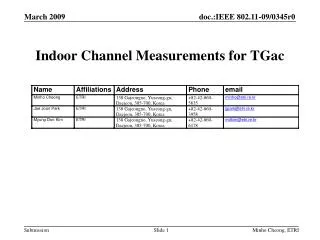
Measurement Information • Several hundred of measurements taken at various locations and scenartios within the company. • Measurements were taken at the lower UNII band (~5.2 GHz) • Receive antennas fixed at a height of ~2m (e.g. AP position) • TX setup moves between measurement positions Metalink
Measurement Set Up • Philosophy: • Full simultaneous MIMO measurements • Relatively slow sampling rate (46MHz)– long sampling period (100msec) • Store all samples and post-process offline • Use wideband transmission signals (>20MHz) • Omni reception and transmission antennas Metalink
Set-Up Block Diagram Metalink
Signal Transmission Setup Metalink
Transmission Antennas Metalink
Reception Antennas Metalink
Sampling Setup Metalink
Indoor Measurement Locations Metalink
Result Snapshot Metalink
Impulse Response (M11-11) Metalink
Time Frequency Response (M11-11) Metalink
RMS Delay Spread (M11-15) Metalink
MIMO Capacity (theoretical) • The theoretical MIMO channel capacity is given by [1]: • Where: C – Capacity [bps/Hz], W- Bandwidth [Hz], P- Power [W], - Noise Variance [W], H- Channel Matrix, - TX Antenna Number Metalink
Real-Environment Calculated Capacity (M11-14) (MIMO Capacity)/2 Metalink
Statistical Findings Metalink
MIMO Capacity Enhancement- NLOS, Dist= 25.6m (M11-XX) Metalink
Periodic Modulation • In nearly all tests, a strong AM-like periodicity is clearly seen. • The period of this modulation was tested to be exactly 100Hz Metalink
Fluorescent Effect Setup Metalink
Fluorescent Effect Setup (cont.) Metalink
Fluorescent Effect Setup (cont.) Metalink
Spectrum at the Various Scenarios Metalink
The Fluorescent Effect • Fluorescent lights become conductive twice every AC power cycle. • During that period, the electromagnetic environment (reflections) are changed. • The channels in such environment exhibit strong AM modulation in all parameters (frequency response, RMS delay spread, capacity, etc.) • We therefore suggest to incorporate this effect into the MIMO channel models as it is one of the major causes of channel time variability Metalink
Conclusions • In typical enterprise scenario 2 antenna MIMO enhances the median capacity by 1.5-2x (NLOS and LOS) • Channels exhibits “slow” variability changes over 100ms (f<10Hz) • In the vicinity of fluorescence lights the channel is modulated by a strong 100/120Hz AM modulation (up to 5dB) Metalink
Summary • A snap-shot of channel measurements in office environment has been presented • Measurements are ongoing and their study shall include topics such as: antenna polarization, channel reciprocity and LOS behavior . • These results are being integrated into the Channel Modeling Sub-Committee led by Erceg. Metalink
References • [1] – Branka Vucetic, “Space-Time Coding”, Wiley& Sons, 2003 Metalink