Download

1 / 18
190 likes | 242 Views
CWC Research Review - ‘03. Whitening-Rotation Based MIMO Channel Estimation. Aditya Jagannatham UCSD. A MIMO Communication System:. r- receive. T X. t - transmit. R x. Receiver. Transmitter. = Antenna. Each channel is characterized by a Complex fading Coefficient

E N D
CWC Research Review - ‘03 Whitening-Rotation Based MIMO Channel Estimation Aditya Jagannatham UCSD
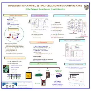
A MIMO Communication System: r- receive TX t - transmit Rx Receiver Transmitter =Antenna • Each channel is characterized by a Complex fading Coefficient • hij represents the channel between the ith receiver and jth transmitter • Arranging these as a matrix we get a ‘Flat Fading’ Channel Matrix ‘H’
System Model: MIMO System H System Model where • Estimating H is the problem of Channel Estimation
Problem Statement Blind Outputs Data MIMO System H Training Training Output Statistical Information
* Constellation Size = 4 - Calls for more robust estimation strategies Issues in Channel Estimation • As the number of channels increases, employing entirely training data to learn the channel would result in poorer spectral efficiency. • -Calls for efficient use of blind and training information • As the diversity of the MIMO system increases, the operating SNR decreases.
Blind Outputs Data MIMO System H Training Output Training Constraint + denotes pseudo-inverse Solution ESTIMATION STRATEGIESTraining Based Estimation
MIMO System H Entirely Data !! Blind Estimation • Estimate channel from DATA • No Training Necessary • Uses information in source statistics
Training Increasing Simplicity Increasing Efficiency Blind Training Vs Blind Estimation
Goals : • Use as few training symbols as possible • Use total information – Training + Blind Total Information Key Idea : • H is decomposed as the product of • A ‘Whitening’ Matrix W and a ‘Rotation’ Matrix Q SemiBlind Estimation – ‘Whitening-Rotation’
Estimating W : W can be estimated Blind from output Data Output Correlation = Estimate Output Correlation Estimate W such that, Q is the non-minimum phase part and cannot be estimated using Second Order Statistics How do we estimate Q ?? Procedure
Advantages Unitary matrix Q parameterized by a significantly lesser number of parameters than M. r x r unitary - r2 parameters r x r complex - 2r2 parameters As the number of receive antennas increases, size of H increases while that of Q remains constant - size of M is r x t - size of Q is t x t Estimating – ‘Q’ the rotation matrix Solution : Estimate Q from the training sequence !
# of Parameters Parameter Sizes of Matrices “Accuracy can be improved by estimating only Q from training data while estimating H blindwithout employing training information” - CR Bound for Channel Estimation error is proportional to the number of parameters.
Minimize the ‘True-Likelihood’ : Goal : subject to : Step 1: Minimize the ‘Modified-Likelihood’ : Step 2: Employ this estimate of Q to minimize the True likelihood Step 3:Using the estimate ofQcompute jointly optimal estimates of W,Q ‘ROSE’ – Rotation Optimization SemiBlind Procedure
Fading coefficients (entries of H) are circular Gaussian random variables (Rayleigh Fading) • Input data is 16 QPSK. • Different H sizes ( 4 X 4, 8 X 4 et al.) have been considered • Input SNR 13 - 14 dB ( ) • Error is. • Estimation error Vs different pilot lengths is plotted for a fixed total length (N) Simulations
Simulation Results H is 8 X 4, SNR = 13 dB, N (Total # Samples) = 400 ROSE performs better for very low Pilot lengths ( 20 symbols approximately)
Simulation Results Total Optimization ROSE performs better for all pilot lengths
A Semi-Blind algorithm has been proposed • Motivation for the formulation has been presented. • Its performance has been studied through simulations. Conclusions
Low Power Scenario H is 8 X 4, Additional - 6db Fade on Channel ROSE now performs better up to PILOT length 60 symbols. Performance (as compared to Training) improves as SNR decreases