Download
1 / 15
150 likes | 312 Views
Update on Q2 Main linac starting gradient, upgrade gradient, and upgrade path. Results of WG5 discussions after feedback from plenary on Tuesday New Option 2 (16 MV/m => 28 MV/m) Enhanced upgrade scenario explorations for options 1 & 2. Three Upgrade Options (with New Names).

E N D
Update on Q2Main linac starting gradient, upgrade gradient, and upgrade path • Results of WG5 discussions after feedback from plenary on Tuesday • New Option 2 (16 MV/m => 28 MV/m) • Enhanced upgrade scenario explorations for options 1 & 2
Three Upgrade Options (with New Names) 1 : (same as last time)”Highest acceptable risk”based on 10% margin • Build tunnel long enough (41km) for one TeV, but install only 500 GeV worth of cryomodules in first 22 km of tunnel for 500 GeV phase. • 35 MV/m installed gradient, 31.5 MV/m operating gradient for 500 GeV (gradient choice rationale discussed earlier). • Fill second part of tunnel (19 km) with 36 MV/m cavities (gradient choice discussed earlier), install more RF/refrigeration 2**: …NEW ”Lower risk”…based on 20% margin • 500 GeV phase: Build tunnel long enough for one TeV (41 km). Populate 24.4 km of tunnel with cavities (35 MV/m installed gradient ) Operate cavities at 20% margin (i.e. 28 MV/m). Increase gradient to 31.5 MV/m over Phase I lifetime, energy climbs to 560 GeV. • Upgrade : Add 36 MV/m cavities in remaining 16.6 km, and add RF and refrigeration for upgrade. 3 : Half-Tunnel (same as last time) • Build first half of tunnel for 500 GeV (22km) and fill it with full gradient cavities (35 MV/m installed gradient, 31.5 MV/m operating gradient, discussed later). • Build second half of tunnel (19km) and add 36 MV/m cavities and RF/refrigeration for upgrade.
Pros/cons of upgrade paths • Initial cost: best = 3: (half-tunnel); worst = Option 2: (20%margin) • Cryomodules + RF + Refrigeration + 2Tunnel “guiding model” costs • Option 1 = 1.16, Option 2 = (1.6) 1.22, Option 3 = 1.0 • Option 2 is less risky, most flexible for physics through higher initial energy reach • Upgrade cost: best = Option 2 (20% margin); worst = Option 3 (half-tunnel). • Option 1 = 0.7, Option 2 = (0.4) 0.63, Option 3 = 0.9 • Total cost (initial + upgrade): worst = 3: (20% margin) • . Option 1 = 1.85, Option 2 = (1.97)1.85, Option 3 = 1.9
WG5 Preferred Choice still is : Option 1 (10% margin) But Option 1 and Option 2 are getting closer ! • Cost Model estimates Option 2 (20%margin) ~1.05 x Option 1 (10% margin) • ( Linac + RF + Cryo + 2tunnels) • Cost Model estimates Option 1 ~ 1.16 x Option 3 • Option 3 (Half-tunnel): Upgrade viability may be questionable, physics impact of digging new tunnel in vicinity of machine (this is a higher level discussion topic than WG5)
A More Optimistic Upgrade ScenarioBased on Weeding out Scheme (Still under discussion) 1 :..”Highest acceptable risk”..based on 10% margin • Build tunnel (41km38.5 km) for one TeV, but install only 500 GeV worth of cryomodules in first 22 km of tunnel. • 35 MV/m installed gradient, 31.5 MV/m operating gradient for 500 GeV (gradient choice rationale discussed earlier). • Upgrade : Fill second part of tunnel (19 km 16.5 km) with 36 MV/m cavities (gradient choice discussed later), install more RF/refrigeration. • Replace the lowest performing cryomodules during upgrade with new cryomodules so that all Phase I modules perform at 35 MV/m..anticipate replacing 10% of existing cryomodules. • Note : total tunnel length shortened by 2.5 km 2: …”Lower risk”…based on 20% margin • Build tunnel long enough for one TeV (38.5 km). Populate 24.4 km tunnel with cavities in phase1 (35 MV/m installed gradient ) Operate cavities at 20% margin (at 28 MV/m) in 500 GeV Phase 1. Increase gradient of installed cavities to 31.5 MV/m over Phase I, energy climbs to 563 GeV. • Upgrade : Add 36 MV/m cavities in 14.1 km, and add RF and refrigeration for upgrade. • Replace the lowest performing cryomodules during upgrade with new cryomodules so that all Phase I modules perform at 35 MV/m..anticipate replacing 10% of existing cryomodules. • Note total tunnel length shortened by 2.5 km
Estimated Cost Impact • Upgrade cost: • Option 1 = 0.7 0.66, Option 2 = 0.63 0.57, Option 3 = 0.9 0.82 • Total cost (initial + upgrade): • Option 1 = 1.85 1.82, Option 2 = 1.85 1.78, Option 3 = 1.9 1.82 • (Includes cost of replacement modules)
Attractive Features of Weeding Concept • Low gradient cryomodules identified during Phase I running • Keep cavity and cryomodule production factory running at low rate to produce 10% replacement modules over lifetime of 500 GeV Phase • About 100 - 120 modules (1200 - 1500 cavities) • Avoids factory production halt and start up problems for upgrade production
Requests to Other Groups • What is the effect of 10%, 20% margin on reliability? • What is the effect of 10% or 20% margin on cost? • Guiding model suggests 10% extra margin has initial project cost penalty of 5% (on linac cost only). • All costs need more detail analysis • How attractive is the weeding out scheme in feasibility, cost, and upgradability ?
Pros/cons of upgrade paths, con’t • Initial schedule Best = 3 half-tunnel, worst = 2 lower risk • Option 3 takes longer to start up due to largest module production and installation • Upgrade schedule: best = 2: lower risk; worst = 3: half-tunnel. Option 2: The extra RF to upgrade half-gradient can be installed while ILC is running if there are 2 tunnels. Option 2 does not require interruption for module production and installation, Option 2 does not take advantage of gradient advances to come • Upgrade viability: • worst = 3: half-tunnel. Has civil construction. Need to check if tunnel boring machines vibrate the ground too much to allow tunneling during running. If so, upgrade is not viable. • Need to move certain installed systems (e.g undulators)
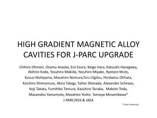
Cavity Gradient/ Shape - 500GeV • Shape Options (to be discussed by Saito) • TESLA • Low-Loss • Re-entrant • Superstructure • Pros/Cons (to be discussed by Saito)
Cavity gradient/ shape - 500GeVRepeat of Friday Summary - Proch • Preferred Choice: TESLA shape • Performance and cost best understood • Gradient Choice 31.5MV/m Based upon • Critical field 41MV/m (TESLA shape) • Practical limit in multi-cells = 90% critical field = 37MV/m (5% sigma spread) • Lower end of present fabrication scatter ( = 5%) • TESLA shape: 35 MV/m • Vert dewar acceptance criteria: 35MV/m or more (some cavities must be reprocessed to pass this) • Operating gradient = 90% x installed gradient = 31.5MV/m • Allows for needed flexibility of operation and commissioning • Gives operating overhead for linac and allows individual module ultimate performance. • Choice of operating gradient does not include fault margin e.g 2 - 5 % additional cryomodules to be determined by availability considerations
Further Comments onstarting cavity gradient - 500GeV • R&D to address remaining risk • Significant R&D necessary to achieve the specified module gradient and spread. • System tests and long-term tests of 35 MV/m modules needed as spelled out by R1 and R2 of TRC • R&D needed in BCD cavity processing & BCD material (though other R&D efforts may prove beneficial e.g. single crystal) • This R&D effort needs to be organized internationally, Discussions underway • Must also address how to industrialize the processing for reliable and reproducible performance
Upgrade gradient choice(depends on shape) discussed on Friday Summary - Proch • Theoretical RF magnetic limit: • Tesla shape: 41 MV/m • LL,RE shape: 47 MV/m • Practical limit in multi-cell cavities -10% • TESLA shape. 37 MV/m • LL, RE shape: expected 42.3 MV/m • Lower end of present fabrication scatter (- 5%) • TESLA shape: 35 MV/m • LL, RE shape: 40 MV/m • Operations margin -10 % • TESLA shape: 31.5 MV/m • LL, RE shape: 36 MV/m
Assume cavities can reach avg of 90% of limit with 5%rms in Vert dewar Most Tesla cavities should be able to reach 35MV/m accept Most LL/RE cavities should be able to reach 40 MV/m accept But note there is a low energy tail that fails 36.9+/-1.85MV/m 42.3+/-2.12MV/m 31.5 41 47 37 35 10% s=5% Eacc [MV/m]