Download
1 / 24
240 likes | 398 Views
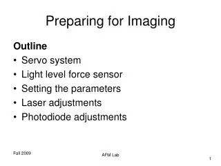
Preparing for Imaging. Outline Servo system Light level force sensor Setting the parameters Laser adjustments Photodiode adjustments. Basic Servo System of an AFM. Basic elements of a AFM servo Close loop control Proportional – Integral (PI) controller.

E N D
Preparing for Imaging Outline • Servo system • Light level force sensor • Setting the parameters • Laser adjustments • Photodiode adjustments AFM Lab
Basic Servo System of an AFM • Basic elements of a AFM servo • Close loop control • Proportional – Integral (PI) controller. AFM Lab
Introduction to Proportional – Integral controller.http://newton.ex.ac.uk/teaching/CDHW/Feedback/ControlTypes.html Proportional Control On-Off Control Proportional+ Integral+ Derivative control Y(t)=Kpє(t) + Ki ∫t-∞є(ζ) dζ AFM Lab
Effect of the PI Controller Setting • When the gains are set too high the system will overcompensate and will lead to a “ringing” at the leading and trailing edges of the features. • When the gains are set too low the system will not adjust the tip fast, blurring the image. AFM Lab
Artifacts Showing the Effect of Servo Optimization on the Image Optimized controller Poorly-optimized controller Example of an artifact created by not having the PID parameters optimized while scanning. In the upper image parameters are optimized, in the lower image parameter are not optimized and the error signal is large. AFM Lab
How to adjust the PI Parameters? • Typically set P=I ~ 5-10% • More to come on the subject! AFM Lab
X-Y Raster Generator Left: Signals output for driving the x and y piezoelectric ceramics in the AFM scanner. Right: Motion of the probe in the x and y axis when the piezoelectric ceramics are activated. AFM Lab
Light Lever Force Sensor Small displacement of the cantilever result in large displacements on the photodetector due to the large “lever arm” of the light path. AFM Lab
Scan • Size: Size of the square • Offset (X and Y): Offset of the square related to the 0,0 origin- Values are limited by the maximum range of the scanner. • Typical values for a run: • Speed (ln/s): 2 • Pixel (pix/ln): 256 • Angle: 0 • Frames: 1 • + AFM Lab
Advanced Tip lift: Keep it checked Overscan % (x and y): 1 Correct for drift (X and Y): 0 Enable Closed loop: Leave it unchecked AFM Lab
Motor Stop at: Stepper motors displacement before t he servo is made active (90% for ACAFM mode, X volts for contact mode (to be defined)) Speed (μm/s): Stepper motors speed, typical 3 Withdraw (μm): Vertical displacement of the probe when the withdraw button is clicked, typical 10 Direct: (leave it unchecked) Position (μm): Relative z position (set it to0 it when the probe is 50 μm above the sample) Step Close/Open: Down or Up movement of the tip Travel: Tip traveling when the steps button are actuated AFM Lab
Scanner AFM Lab
Detector Assembly • Detector assembly, top and bottom views AFM Lab
Scanner Mounting • Scanner mounting jig with nose assembly and spring key; scanner in mounting jig • Nose assembly removal tool AFM Lab
Nose Amplifier Assembly • Using the nose assembly removal tool AFM Lab
Inserting the Nose Assembly • Applying even, vertical pressure at the edges to insert the nose assembly. AFM Lab
Nose Assembly Removing • Spring key • Do not use tweezers to remove a nose assembly. Doing so can place damaging lateral forces on the scanner. AFM Lab
Probe Mounting • Probe properly situated on AFM nose assembly AFM Lab
Laser Adjustment • Use the scanner knobs to optimize the laser spot Goal: to adjust the laser bean on the tip of the cantilever “F” corresponds to the goal which has to be met. The laser beam is bouncing just on the tip of the cantilever AFM Lab
Photodiode detector operation AFM Lab
Photodiode Adjustment • Laser Alignment window in PicoView for AAC Mode • Align spot to yellow, dotted line for Contact Mode AFM Lab
Getting an Image • Enter scan Speed 1-2 lines/sec. The slower the “speed” the better the resolution • Select from X list “256”. The higher the number the better the resolution • Set “Size” • Set “Angle” to “0”. The “Angle” adjust the direction where the tracking is going to be done. “0” is parallel to “X” AFM Lab
Fine-tuning the Image • Set Servo Gain I=P=10% • Note the “Deflection” value • In the “Setpoint” enter a value slightly above this number • In ACAFM the closer the Setpoint is to “0”, the more force the cantilever exerts on the sample • Use the “Up” arrow to increase the voltage. At one point, the indicator will change from “green” to “red”. Use the “down” arrow to bring the indicator to the “green” zone. This is the highest value which will keep the tip and sample in contact. • During the scan you may decide to lower the value of the setpoint to improve the resolution of the image. AFM Lab