Download
1 / 15
150 likes | 324 Views
Verilog primjer / * 4 to 1 MUX (16 data in -out ) */ module mux_4to1(Y, A, B, C, D, sel); output [15:0] Y; input [15:0] A, B, C, D; input [1:0] sel; reg [15:0] Y; // izlaz tipa reg always @(A or B or C or D or sel) case ( sel ) // ovisno o 2 bita sel 2'b00: Y = A; 2'b01: Y = B;

E N D
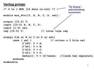
Verilog primjer /* 4 to 1 MUX (16 data in-out) */ module mux_4to1(Y, A, B, C, D, sel); output [15:0] Y; input [15:0] A, B, C, D; input [1:0] sel; reg [15:0] Y; // izlaz tipa reg always @(A or B or C or D or sel) case ( sel ) // ovisno o 2 bita sel 2'b00: Y = A; 2'b01: Y = B; 2'b10: Y = C; 2'b11: Y = D; default: Y = 16'hxxxx; //inače hex nepoznato endcase endmodule Tip dugog i jednolinijskog komentara
Verilog primjer // 1-bit Register module Reg1(clk, I, enb, Q);input clk;input I, enb;output Q;reg Q; always @ (posedge clk) begin if( enb == 1 ) Q <= I; endendmodule nonblocking assign (isti vremenski trenutak za cijeli oblikovani sustav)
Verilog primjer /* 32 bit register with an asynchronous reset (active low) */ module Reg32(Q, D, clk, reset_); output [31:0] Q; input [31:0] D; input clk, reset_; reg [31:0] Q; // izlaz tipa reg always @(posedge clk or negedge reset) if (!reset_) // ako reset (neg) stavi 0 Q <= 32'b0; // non blocking assign else Q <= D; // inače stavi što je na ulazu endmodule ! logical NOT
Verilog primjer // 2x4 Decoder // Truth table for 2x4 Decoder // A B | D3 D2 D1 D0 //---------+----------------- // 0 0 | 0 0 0 1 // 0 1 | 0 0 1 0 // 1 0 | 0 1 0 0 // 1 1 | 1 0 0 0 module Decoder(A, B, D); input A, B; output [3:0] D; reg [3:0] D; // nastavak na slijedećoj slici
Verilog primjer // nastavak 2x4 Dekoder always @ (A or B) begin if( A == 0 && B == 0 ) D <= 4'b0001; // non blocking assign else if ( A == 0 && B == 1 ) D <= 4'b0010; else if ( A == 1 && B == 0 ) D <= 4'b0100; else D <= 4'b1000; end endmodule
Verilog primjer • // 4-bit Adder • module Adder(A, B, Result); • input [3:0] A; • input [3:0] B; • output [3:0] Result; • reg [3:0] Result; • always @ (A or B) • begin • Result <= A + B; • end • endmodule • **************************************** • Napomena: • “Register” operandi su “unsigned” • Ako je jedan operand nepoznat (“x”), rezultat je nepoznat (“x”) • “Carry” se ignorira u ovom primjeru
Verilog primjer • // Adder, uporaba “parameter” i “assign” naredbe • module adder (sum, a, b); • parameter WIDTH = 7; • // ovdje 8 bita, može se mijenjati • input [WIDTH:0] a, b; • output [WIDTH:0] sum; • assign sum = a + b; • endmodule • ************************************************ • Napomena: • Naredbom “assign” će se promijeniti “sum” ako se promijene “a” ili “b” BILO KADA (a ne kao što to u drugim prikazanim slučajevima određuje “blocking” i “nonblocking” pridruživanje) . Ovdje korištena naredba “assign” prikazuje doslovnu karakteristiku kombinacijske logike (kao da su elementi čvrsto i stalno povezani žicama).
Verilog primjer // jednobitno zbrajalo, 3 bita na ulazu module oneBitFullAdder(cOut, sum, aIn, bIn, cIn); output cOut, sum; input aIn, bIn, cIn; assign sum = aIn ^ bIn ^ cIn, cOut = (aIn & bIn) | (bIn & cIn) | (aIn & cIn); endmodule // operator “^“ je “bitwise XOR” // operator “|” je “bitwise” OR // operator “&” je bitwise AND // operator “~” je bitwise komplement *************************************** Napomena: Naredba “assign” je niže razine apstrakcije nego “blocking” i “nonblocking” pridruživanje. Bliže je opisu izvedbe digitalnih sustava logičkim sklopovima.
Verilog primjer /* 4-bit Multiplier, consists of 2 4-bit inputs A and B, and an 8-bit output */ module Multiplier(A, B, Result); input [3:0] A; input [3:0] B; output [7:0] Result; reg [7:0] Result; always @ (A or B) begin Result <= A * B; end endmodule
Bin inputs: A B C D A=23, B=22, C=21, D=20 Output: e LED only for HEX character Ex. 1 1 0 1 = 13DEC = HEX char. “d” e LED = 1 (ON) Verilog primjer e AB CD
Qi zi Kombinacijska logika xi clock Trenutno stanje (sekvencijski dio – bistabili) 0/000 0/010 reset in/out (in 1 bit, out 3 bita) 1/100 1/100 1/101 1/110 1/110 F D C B A E 0/000 0/010 reset ?/101 0/000 Verilog primjer - FSM QNEXT = f(x, Q) Mealy: z = g(Q, x) Moore z = h(Q) jedan “module” dvije “always” naredbe (kombinacijska i sekvencijska) zajedno definiraju rad FSM-a
Verilog primjer - FSM module fsm (i, clock, reset, out); input i, clock, reset; output [2:0] out; // output 3 bita reg [2:0] out; reg [2:0] currentState, nextState; //3 bita OK parameter [2:0] A = 0, // state assignments B = 1, // for current/next C = 2, D = 3, E = 4, F = 5; //1st always: comb logic, out and nextState functions always @(i or currentState) case (currentState) A: begin nextState = (i == 0) ? A : B; out = (i == 0) ? 3'b000 : 3'b100; end ako se promijeni If true then, else
Verilog primjer - FSM • B: // analogno za B, C, D, E • C: • D: • E: • F: begin • nextState = D; • out = (i == 0) ? 3'b101 : 3'b101; • end • default: begin // if undeined states,go to A • nextState = A; • out = (i == 0) ? 3'bxxx : 3'bxxx; • end //out = don’t care • endcase • // sequential part • always @(posedge clock or negedge reset) • if (~reset) // reset = low • currentState <= A; • else // posedge clock • currentState <= nextState; • endmodule nonblocking = acress the whole design
Verilog primjer – FSM (malo drugačije označavanje) neg. edge reset pos. edge 1 00/0 0 0 01/1 clock 1 11/0 1 0 If in state 1 out is generated. Moore FSM: out is a function of state only State Input module fsm(out, in, clock, reset); output out; input in, clock, reset; reg out; reg [1:0] currentState, nextState; // combination portion // * * * // sequential portion // * * * endmodule
// combination portion always @(in or currentState) begin out = ~currentState[1] & currentState[0]; // out = 1 only for state 01 nextState = 0; if (currentState == 0) if(in) nextState = 1; //else stay in 0 if (currentState == 1) if (in) nextState = 3; //else go to 0 if (currentState == 3)begin if (in) nextState = 3; else nextState = 1; end end // the sequential portion always @(posedge clock or negedge reset) begin if (~reset) currentState <= 0; // as long as res=0 else currentState <= nextState; // as D type bistable end Bit select = 01 non blocking

![Suppose f ( x,y,z ) is bounded f or all ( x,y,z ) in a box B = [ a,b ][ c,d ][ p,q ].](https://cdn1.slideserve.com/3217068/slide1-dt.jpg)