Download
1 / 30
300 likes | 415 Views
Sketching. Purpose Techniques Size and Proportion Alphabet of Lines Projections References. Contents Click Shape to go to section. Purpose.

E N D
Purpose Techniques Size and Proportion Alphabet of Lines Projections References Contents Click Shape to go to section.
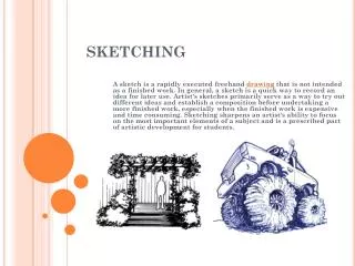
Purpose • The main purpose of sketching is to convey ideas. Engineers have to use sketches to brainstorm ideas, as well as, to show others what they are working on or what should be designed. Sketches are also used to document measurements from the field before they are produced as solid models on the computer.
Practice Practice Practice Practice Practice Practice Practice Practice Do you want to be a good sketcher?
Purpose • Proper documentation in a Lab Record Book (LRB) is essential. When proper documentation is made, ideas are not lost and projects can be duplicated. Figure 1 is a sample from an LRB where a sketch was made and notes as well as dimensions have been documented.
LRB Sample Sketch Shows design details Size requirements. Title Initialed and dated.
TECHNIQUES Contents
Sketching Techniques • Line Types: Inclined Line Vertical Line Horizontal Line
Run = 4 Rise = 2 Sketching Techniques • Finding the slope angle of an inclined line: Equation: tans = RISE/RUN Rise = 2, Run = 4 (count the squares) tans = 2/4 (tans= .5 s = arctan .5 Note: Rise and Run units do not matter (As long as the units are the same). You are finding an angle. In the above case, we are counting grid boxes.
Sketching Techniques • Sketching a Line.
Sketching Techniques • Sketching an Arc
Sketching Techniques • Sketching an Arc
1) Setup the diameter 2) Square in the diameter 3) Sketch diagonals Sketching Techniques: Circle
Sketching Technique: Ellipse Draw a rectangle the width and height of the ellipse Mark the centers of Each side Draw the ellipse Draw Diagonal linesfrom each center mark Mark the centers of each triangle created bythe diagonals
Size and Proportion • Although you have learned to draw lines and arcs, you can not communicate properly until you understand how to sketch with the correct size and proportion. Without proper size and proportion your sketch will not look right. • Size: Length, width, height, distance. How big is the object you are sketching? • Proportion: If two objects are five feet apart in real life, then those two objects must appear to be five feet apart in your sketch.
Hold your pencil at arms length as you see in Figure 2. Use the top of the pencil and your thumb as a distance for the height of the window. This distance will be used as a reference for sketching the rest of the house as we did in the house on the next slide. Size and Proportion • How to create proper size and proportion. Technique I • Using a pencil to measure. Figure 2
Figure 3 Size and Proportion • How to create proper size and proportion. Technique I • Using a pencil to measure. As you see in the completed house in Figure 3, the units of the numbered dimensions are in windows. You should also notice that the use of graph paper also helps in creating proper size and proportion.
Figure 4 Size and Proportion • How to create proper size and proportion. Technique II • Boxing in the sketch. In Figure 4 we are sketching a chair. We sketch the boxes to the largest outside dimensions of our final object. Notice that light construction lines are also used to help guide us to the proper size and proportion.
Figure 5 Size and Proportion • How to create proper size and proportion. Technique II • Boxing in the sketch. Finally we use our sketching techniques for drawing arcs, lines and circles to complete our chair in Figure 5. Notice the box we started with is still existent as light construction lines. These are our guides for proportion and size.
ALPAHBET OF LINES Contents
Object Line: Thick lines about .6mm(.032in) that show the visible edges of an object. Alphabet of Lines Short Break Line: A freehand drawn line that shows where a part is broken to reveal detail behind the part or to shorten a long continuous part. (See example of Long Break Line on the next slide.) Hidden Line: Lines used to show interior detail that is not visible from the outside of the part. Center Line: Lines that define the center of arcs, circles, or symmetrical parts. They are half as thick as an object line. Section Lines: Lines are used to define where there is material after a part of the object is cut away. Construction Line: Very lightly drawn lines used as guides to help draw all other lines and shapes properly. Usually erased after being used.
Alphabet of Lines Long Break Lines: Break lines are used to either show detail or as in this case they can be used to shorten very long objects that do not change in detail. Notice that this part is 12” long however we have shortened the drawing with break lines to use our space more efficiently. Dimension Lines: Lines that are used to show distance. Arrows are drawn on the ends to show where the dimension line starts and ends. The actual distance is usually located in the middle of this line to let you know the distance being communicated. Dimension lines are used in conjunction with extension lines to properly dimension objects. Cutting Plane Line: A line used to designate where a part has been cut away to see detail. The arrows should point in the direction that you are looking at the cutout. Extension Lines: Lines used to show where a dimension starts and stops on an object. Used with dimension lines to properly dimension an object. The line is 1/16” away from the part as to not get confused with the object lines Leader Lines: Leader lines are used to show dimensions of arcs, circles and to help show detail. An arrow head is used to point to the part you are dimensioning and the line Comes off the arrow point usually at a 45 degree angle. At the end of this line a horizontal line is drawn with a descriptive note How many lines from the previous slide can you identify here?
Alphabet of lines Phantom Lines: Phantom lines are used to identify alternate positions that a part my take up. In this example we are using Phantom lines to show that the door handle may only move 45 degrees from it’s horizontal position. How many lines from the previous 2 slides can you identify here?
One View Selection Two views will be identical Uniform shape. All dimensions easily shown on one view.
One View Selection It is also possible to have one view drawings of objects that are flat and have even thickness. Gauges and gaskets are two such objects. We have a gauge here on the left.
Precedence of Lines An object line here takes precedence over the center line. However we draw short thin lines beyond the object to show there is a center line underneath the object line. Object lines took precedence over the hidden lines you would see from the hole. The center line in the top view would show the depth of the hole as well as the right side view.
References • Madsen, David A., Shumaker, Terence M., Stark, Catherine, Turpin, J. Lee, Engineering Drawing and Design Second Edition,Delmar Publishers, 1996, ISBN 0-8273-6720-1. • Brown, David, You Can Draw,North Light Books, Cincinnati, Ohio, 1986, ISBN 0-89134-216-8. • Olivo, Dr. C. Thomas, Olivo, Thomas P., Basic Blueprint Reading and Sketching Sixth Edition, Delmar Publishers Inc., 1993, ISBN 0-8273-5740-0. • Johnson, Cindy M., Lockhart, Shawna D., Engineering Design Communication, Prentice Hall, 2000, ISBN 0-201-33151-9.
References • Spencer, Henry Cecil, Dygdon, John Thomas, Novak, James E; Basic Technical Drawing 6th Edition; Glencoe McGraw Hill; New York, New York,1995, ISBN 0-02-685660-3.
Practice Practice Practice Practice Practice Practice Practice Practice Do you want to be a good sketcher? First Slide