Download
1 / 13
190 likes | 464 Views
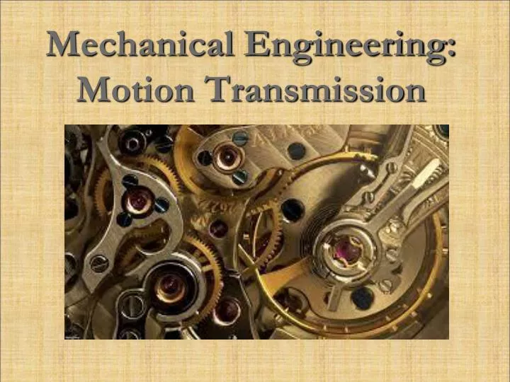
Mechanical Engineering: Motion Transmission. Friction Gears (wheels). Wheels that do NOT have teeth. Wheels move because of friction between them. T ransmit rotational motion between two or more parts that are close together. Rotational direction reverses in side-to-side contact.

E N D
Friction Gears (wheels) • Wheels that do NOT have teeth. • Wheels move because of friction between them. • Transmit rotational motion between two or more parts that are close together. • Rotational direction reverses in side-to-side contact. • Easier to assemble and cost less to make. • Disadvantage: Gears tend to slip.
Friction Gears (wheels) • The larger diameter of the gear the slower it rotates. • Made of high friction materials like rubber. • Can be positioned along parallel, perpendicular, or other rotational axis depending on need.
Belt & Pulley • At least two wheels are connected together by a belt. • Wheels are toothless and therefore called pulleys. • Used to transmit rotational motion between parts that are further apart. • When more than two pulleys are used, only the pulley that touches the same side of the belt will turn in the same direction. • Can reverse motion.
Belt & Pulley • The often contains a groove allowing the belt to function smoothly and securely. • The belt must stick or adhere to the pulley to avoid slipping. • The larger the pulley the slower it turns.
Gear Assembly • At least two gears that meet and fit perfectly into one another. • Slippage between gears is prevented by interlocking gear teeth. • Used to transmit motion between parts that are close together. • Can reverse motion.
Gear Assembly • For the two or more gears to work together, the teeth of each gear need to be the same size, shape, direction (straight or helical) and must be equally spaced. • The positioning of the gears can vary: Parallel (Straight gears are used) or Perpendicular (Bevel gears). • The more teeth on a gear, the slower the rotation speed and vice versa. • The smaller the diameter of the gear, the faster the rotation and vice versa.
Chain and Sprocket Wheels • The teeth on the Sprocket Wheels must be identical as ONE chain must fit on all sprockets in the system. • The links in the chain are designed to fit securely on the teeth of the sprockets. • This system requires lubrication such as grease or oil on a regular basis to avoid wear. • The larger the sprocket the slower it turns and vice versa.
Wheel & Worm Gear • Made from a single worm (screw) that rotates. This motion is transmitted to one or more wheel gears. • The worm can turn continuously. • Movement is very slow, however. • Motion CANNOT be reversed.
Wheel & Worm Gear • The groove on the worm (screw component) must fit the wheel teeth so that they fit together and motion is possible. • The drive component is always the worm gear and this is what makes this system non-reversible.