Download
1 / 64
640 likes | 647 Views
Design is a creative activity that determines the major characteristics of a system. It focuses on module view, modularity, coupling, and cohesion. This article explores these concepts and their impact on system development.

E N D
Software Design • Design activity begins with a set of requirements, and maybe an architecture • Design done before the system is implemented • Design focuses on module view – i.e. what modules should be in the system • Module view may have easy or complex relationship with the C&C view • Design of a system is a blue print for implementation • Often has two levels – high level (modules are defined), and detailed design (logic specified)
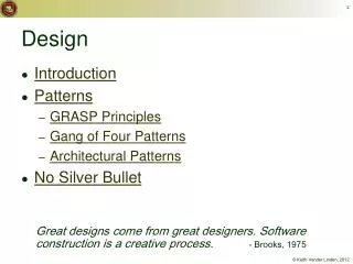
Design… • Design is a creative activity • Goal: to create a plan to satisfy requirements • Perhaps the most critical activity during system development • Design determines the major characteristics of a system • Has great impact on testing and maintenance • Design document forms reference for later phases • Design methodology – systematic approach for creating a design
Design Concepts • Design is correct, if it will satisfy all the requirements and is consistent with architecture • Of the correct designs, we want best design • We focus on modularity as the main criteria (besides correctness)
Modularity • Modular system – in which modules can be built separately and changes in one have minimum impact on others • Modularity supports independence of models • Modularity enhances design clarity, eases implementation • Reduces cost of testing, debugging and maintenance
Modularity • Cannot simply chop a program into modules to get modularly • Need some criteria for decomposition – coupling and cohesion are such criteria
Coupling • Independent modules: if one can function completely without the presence of other • Independence between modules is desirable • Modules can be modified separately • Can be implemented and tested separately • Programming cost decreases • In a system all modules cannot be independent • Modules must cooperate with each other • More connections between modules • More dependent they are • More knowledge about one module is required to understand the other module. • Coupling captures the notion of dependence
Coupling… • Coupling between modules is the strength of interconnections between modules • In general, the more we must know about module A in order to understand module B the more closely connected is A to B • "Highly coupled" modules are joined by strong interconnection • "Loosely coupled" modules have weak interconnections
Coupling… • Goal: modules as loosely coupled as possible • Where possible, have independent modules • Coupling is decided during high level design • Cannot be reduced during implementation • Coupling is inter-module concept • Major factors influencing coupling • Type of connection between modules • Complexity of the interface • Type of information flow between modules
Coupling – Type of connection • Complexity and obscurity of interfaces increase coupling • Minimize the number of interfaces per module • Coupling is minimized if • Only defined entry of a module is used by others • Information is passed exclusively through parameters • The number of interfaces is minimized • Coupling increases if • Internals of a module are directly used • Shared variables employed for communication • Indirect and obscure interface are used
Coupling – interface complexity • Coupling increases with complexity of interfaces eg. number and complexity of parms • Interfaces are needed to support required communication • Often more than needed is used eg. passing entire record when only a field is needed • Keep the interface of a module as simple as possible
Coupling – Type of Info flow • Coupling depends on type of information flow • Two kinds of information: data or control. • Transfer of control information • Action of module depends on the information • Makes modules more difficult to understand • Transfer of data information • Module can be treated as input-output function • Lowest coupling: interfaces with only data communication • Highest: hybrid interfaces
Coupling - Summary Coupling Interface Type of Type of complexity connections communication Low Simple to module data obvious by name High complicated to internal Hybrid obscure elements
Cohesion • Coupling characterized the inter-module bond • Reduced by minimizing relationship between elts of different modules • Another method of achieving this is by maximizing relationship between elts of same module • Cohesion considers this relationship • Interested in determining how closely the elements of a module are related to each other • In practice both are used
Cohesion… • Cohesion of a module represents how tightly bound are the elements of the module • Gives a handle about whether the different elements of a module belong together • High cohesion is the goal • Cohesion and coupling are interrelated • Greater cohesion of modules, lower coupling between module • Correlation is not perfect.
Levels of Cohesion • There are many levels of cohesion. • Coincidental • Logical • Temporal • Communicational • Sequential • Functional • Coincidental is lowest, functional is highest • Scale is not linear • Functional is considered very strong
Coincidental cohesion • occurs when there is no meaningful relationship among the elements of a module. • If a module is created to save duplicate code by combining some part of code that occurs at many different places.
Logical cohesion • if there is some logical relationship between the elements of a module, and the elements perform functions that fall in the same logical class. • Example: module that performs all the inputs or all the outputs. if we want to input or output a particular record.
Temporal cohesion • the same as logical cohesion, except, the elements are also related in time and are executed together. • Temporal cohesion is higher than logical cohesion, because the elements are all executed together.
Procedurally cohesive • contains elements that belong to a common procedural unit. • Example, a loop or a sequence of decision statements in a module may be combined to form a separate module. • often occur when modular structure is determined from some form of flowchart.
Communicational cohesion • has elements that are related by a reference to the same input or output data. • Communicationally cohesive modules may perform more than one function.
Sequential cohesion • When the elements are together in a module because the output of one forms the input to another.
Functional cohesion • is the strongest cohesion. • all the elements of the module are related to performing a single function. • modules accomplishing a single goal are also included.
Determining Cohesion • Describe the purpose of a module in a sentence • Perform the following tests 1. If the sentence has to be a compound sentence, contains more than one verbs, the module is probably performing more than one function. Probably has sequential or communicational cohesion. 2. If the sentence contains words relating to time, like "first", "next", "after", "start" etc., the module probably has sequential or temporal cohesion.
3.If the predicate of the sentence does not contain a single specific object following the verb, the module is probably logically cohesive. Eg "edit all data", while "edit source data" may have functional cohesion. 4. Words like "initialize", "clean-up" often imply temporal cohesion. • Functionally cohesive module can always be described by a simple statement
Open-closed Principle • Besides cohesion and coupling, open closed principle also helps in achieving modularity • Principle: A module should be open for extension but closed for modification • Behavior can be extended to accommodate new requirements, but existing code is not modified • I.e. allows addition of code, but not modification of existing code • Minimizes risk of having existing functionality stop working due to changes – a very important consideration while changing code • Good for programmers as they like writing new code
Summary • Goal of designing is to find the best possible correct design • Modularity is the criteria for deciding quality of the design • Modularity enhanced by low coupling, high cohesion, and following open-closed principle
Program Structure and Structure Charts • Every program has a structure • Structure Chart - graphic representation of structure • SC represents modules and interconnections • Each module is represented by a box • If A invokes B, an arrow is drawn from A to B • Arrows are labeled by data items • Different types of modules in a SC • Input, output, transform and coordinate modules • A module may be a composite
Structure charts… • SC shows the static structure, not the logic • Different from flow charts • Major decisions and loops can be shown • Structure is decided during design • Implementation does not change structure • Structure effects maintainability • SDM aims to control the structure
STRUCTURED DESIGN METHODOLOGY • SDM views software as a transformation function that converts given inputs to desired outputs • The focus of SD is the transformation function • Uses functional abstraction • Goal of SDM: Specify functional modules and connections • Low coupling and high cohesion is the objective Transformation functions Output Input
Steps in SD • Draw a DFD of the system • Identify most abstract inputs and most abstract outputs • First level factoring • Factoring of input, output, transform modules • Improving the structure
1. Data Flow Diagrams • SD starts with a DFD to capture flow of data in the proposed system • DFD is an important representation; provides a high level view of the system • Emphasizes the flow of data through the system • Ignores procedural aspects • (Purpose here is different from DFDs used in requirements analysis, thought notation is the same)
Drawing a DFG • Start with identifying the inputs and outputs • Work your way from inputs to outputs, or vice versa • If stuck, reverse direction • Ask: "What transformations will convert the inputs to outputs" • Never try to show control logic. • If thinking about loops, if-then-else, start again • Label each arrow carefully • Make use of * and +, and show sufficient detail • Ignore minor functions in the start • For complex systems, make dfg hierarchical • Never settle for the 1st dfg
Step 2 of SD Methodology • Generally a system performs a basic function • Often cannot be performed on inputs directly • First inputs must be converted into a suitable form • Similarly for outputs - the outputs produced • by main transforms need further processing • Many transforms needed for processing inputs and outputs • Goal of step 2 is to separate such transforms from the basic transform centers
Step 2… • Most abstract inputs: data elements in dfg that are furthest from the actual inputs, but can still be considered as incoming • These are logical data items for the transformation • May have little similarity with actual inputs. • Often data items obtained after error checking, formatting, data validation, conversion etc.
Step 2… • Travel from physical inputs towards outputs until data can no longer be considered incoming • Go as far as possible, without loosing the incoming nature • Similarly for most abstract outputs • Represents a value judgment, but choice is often obvious • Bubbles between mai and mao: central transforms • These transforms perform the basic transformation • With mai and mao the central transforms can concentrate on the transformation
Step 2… • Problem View: Each system does some i/o and some processing • In many systems the i/o processing forms the large part of the code • This approach separates the different functions • subsystem primarily performing input • subsystem primarily performing transformations • subsystem primarily performing output presentation
3. First Level Factoring • First step towards a structure chart • Specify a main module • For each most abstract input data item, specify a subordinate input module • The purpose of these input modules is to deliver to main the mai data items • For each most abstract output data element, specify an output module • For each central transform, specify a subordinate transform module • Inputs and outputs of these transform modules are specified in the DFD