Download
1 / 27
290 likes | 474 Views
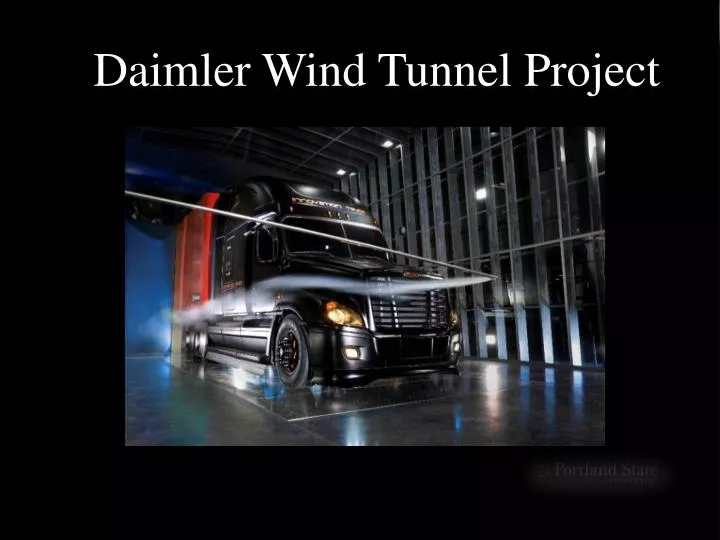
Daimler Wind Tunnel Project. Project Review. Capstone Team Andre Nylund Chris Grewell Craig Lechtenberg Fadel Al Jutail Matt Melius Mufeed Yacoub Team Advisor Dr. Raul Bayoán Cal Customer Daimler Trucks North America. Project Review. Tunnel Details 12,000 sq. ft. facility

E N D
Project Review • Capstone Team • Andre Nylund • Chris Grewell • Craig Lechtenberg • Fadel Al Jutail • Matt Melius • Mufeed Yacoub • Team Advisor • Dr. Raul Bayoán Cal • Customer • Daimler Trucks North America
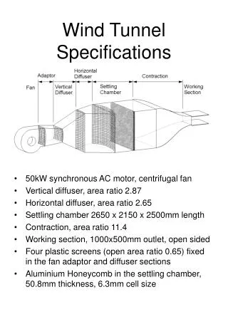
Project Review Tunnel Details • 12,000 sq. ft. facility • Wind speeds up to 65 mph • 30ft long test section 21ft wide 26ft tall
Project Review • Pressure sensitive floor for calculating trucks drag coefficient. • Smoke wand for flow visualization Tunnel Details • Rotating floor panel to test various angles of attack
Issues with Current Smoke Testing Equipment • Smoke wand placement is limited by the length of the wand
Issues with Current Smoke Testing Equipment • Smoke wand placement is limited by the length of the wand • Wand is manually held from outside the tunnel then angled into position, requiring extra personal to perform testing
Issues with Current Smoke Testing Equipment • Smoke wand placement is limited by the length of the wand • Wand is manually held from outside the tunnel then angled into position, requiring extra personal to perform testing • Manual control makes repeatable testing of an area difficult
Issues with Current Smoke Testing Equipment • Smoke wand placement is limited by the length of the wand • Wand is manually held from outside the tunnel then angled into position, requiring extra personal to perform testing • Manual control makes repeatable testing of an area difficult • Flexibility of current wand reduces accuracy of smoke placement during testing
Project Review Mission Statement: Improve smoke testing methods • Increase the testable area within the wind tunnel • Increase stability of the system • Deliver smoke to location of interest accurately • Provide these requirements while maintaining negligible aerodynamic impact to test region • Design and delivery of final product by June,6th
Concept Design Wand Support Rollers Drive Motor Wind Tunnel Wall Vertical Rails Vertical Carriages Smoke Wand Horizontal Rail Horizontal Carriage
Support Structure : Stable, inexpensive, and Easily Manufactured • Traverse System: • 18’ x 16’ of testable area • 10ft/min vertical rise, 20ft/min horizontal motion • Easily removed from wind tunnel when not in use • Smoke Delivery: • Simple to maintain • Easy to use • +/- 0.5” in expected accuracy with high repeatability • Sealing System: Permanent System to prevent pressure related disturbances in test section • Roller Box: Provides adjustability and stability to the smoke boom during testing. System Overview
System Overview Smoke Control System
Support Structure • I-beams provide vertical support and trolley guidance • 5”x5” Box beam for horizontal stability and mounting interface for drive system Horizontal 5x5 Box Tubing 10W26 I-beam Base Plates
Lifting System • Parallel Ball Screw Assembly • 2hp Motor • Two Inverted Actuators w/ 12:1 gear ratio • Rise time of 10ft/min Actuator Miter Box Pillow Block Drive Shaft Ball Screw
Attaches to the vertical drive system • Controls the horizontal movement of smoke wand Horizontal Location System Left Trolley Right Trolley Ball Screw Nut Bracket Linear Actuator
Horizontal Location System Two key features • 4 adjustable and 4 fixed wheels between the webs for vertical motion • 4 flange rollers to control “walking” • 12 points of contact Web adjustment wheels Flange rollers
Attaches to the Horizontal Location System • Controls the smoke wand in and out of the wind tunnel Roller Housing Housing Clamps Roller Box Roller Assemblies
Roller Box 3 key features • Isolate reaction forces Roller assemblies 3x4.75in Carbon Fiber Tube
Roller Box Adjustment Screws 3 key features • Isolate reaction forces • Allow for different wand profiles 3in Carbon Fiber Tube
Roller Box 3 key features • Isolate reaction forces • Allow for different wand profiles • Adjust the angle of attack Housing Clamps Housing Clamp bolts Housing
An Aerolab Smoke Generator attached to the Horizontal Support produces smoke by burning oil • The smoke wand will be supported at the end of a 19ft carbon fiber smoke wand support with a rapid prototype collet Smoke System
Maintains pressure differential between inside and outside of the wind tunnel • slides vertically via lifting system • Lifting rod design accommodates tunnel wall angle. Wall Seal Shutter Lifting Rod Bearing Lifting Rod Penetration Plate
Documentation • Documentation provided to Customer: • System assembly • Parts list • Custom Part Drawings