Download
1 / 45
450 likes | 615 Views
CS 203A Advanced Computer Architecture. Lecture 5 Section A.8 Branch Hazards and Dynamic Scheduling via scoreboarding. Instructor: L.N. Bhuyan. Control Hazards. Branch problem: branches are resolved in EX stage 2 cycles penalty on taken branches

E N D
CS 203AAdvanced Computer Architecture Lecture 5Section A.8Branch Hazards and Dynamic Schedulingvia scoreboarding Instructor: L.N. Bhuyan
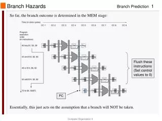
Control Hazards • Branch problem: • branches are resolved in EX stage 2 cycles penalty on taken branches Ideal CPI =1. Assuming 2 cycles for all branches and 32% branch instructions new CPI = 1 + 0.32*2 = 1.64 • Solutions: • Reduce branch penalty: change the datapath – new adder needed in ID stage. • Fill branch delay slot(s) with a useful instruction. • Fixed branch prediction. • Static branch prediction. • Dynamic branch prediction.
Control Hazards – branch delay slots • Reduced branch penalty: • Compute condition and target address in the ID stage: 1 cycle stall. • Target and condition computed even when instruction is not a branch. • Branch delay slot filling: move an instruction into the slot right after the branch, hoping that its execution is necessary. Three alternatives (next slide) Limitations: restrictions on which instructions can be rescheduled, compile time prediction of taken or untaken branches.
Delayed Branch add M1 ,M2,M3 sub M4, M5,M6 beq M1, M4, Exit or M8, M9 ,M10 xor M10, M1,M11 Exit: Example Nondelayed vs. Delayed Branch Nondelayed Branch or M8, M9 ,M10 add M1 ,M2,M3 sub M4, M5,M6 beq M1, M4, Exit xor M10, M1,M11 Exit:
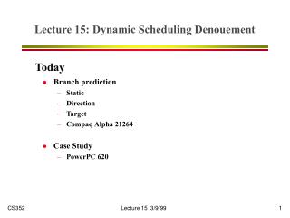
Control Hazards: Branch Prediction • Idea: doing something is better than waiting around doing nothing • Guess branch target, start executing at guessed position • Execute branch, verify (check) your guess + minimize penalty if guess is right (to zero) • May increase penalty for wrong guesses • Heavily researched area in the last 15 years • Fixed branch prediction. Each of these strategies must be applied to all branch instructions indiscriminately. • Predict not-taken (47% actually not taken): • continue to fetch instruction without stalling; • do not change any state (no register write); • if branch is taken turn the fetched instruction into no-op, restart fetch at target address: 1 cycle penalty.
Control Hazards: Branch Prediction • Predict taken (53%): more difficult, must know target before branch is decoded. no advantage in our simple 5-stage pipeline. • Static branch prediction. • Opcode-based: prediction based on opcode itself and related condition. Examples: MC 88110, PowerPC 601/603. • Displacement based prediction: if d < 0 predict taken, if d >= 0 predict not taken. Examples: Alpha 21064 (as option), PowerPC 601/603 for regular conditional branches. • Compiler-directed prediction: compiler sets or clears a predict bit in the instruction itself. Examples: AT&T 9210 Hobbit, PowerPC 601/603 (predict bit reverses opcode or displacement predictions), HP PA 8000 (as option).
Control Hazards: Branch Prediction • Dynamic branch prediction • Based on the history of a particular branch - Later
MIPS FP Pipe Stages FP Instr 1 2 3 4 5 6 7 8 … Add, Subtract U S+A A+R R+S Multiply U E+M M M M N N+A R Divide U A R D28 … D+A D+R, D+R, D+A, D+R, A, R Square root U E (A+R)108 … A R Negate U S Absolute value U S FP compare U A R Stages: M First stage of multiplier N Second stage of multiplier R Rounding stage S Operand shift stage U Unpack FP numbers • A Mantissa ADD stage • D Divide pipeline stage • E Exception test stage
R4000 Performance • Not ideal CPI of 1: • Load stalls (1 or 2 clock cycles) • Branch stalls (2 cycles + unfilled slots) • FP result stalls: RAW data hazard (latency) • FP structural stalls: Not enough FP hardware (parallelism)
FP Loop: Where are the Hazards? Loop: LD F0,0(R1) ;F0=vector element ADDD F4,F0,F2 ;add scalar from F2 SD 0(R1),F4 ;store result SUBI R1,R1,8 ;decrement pointer 8B (DW) BNEZ R1,Loop ;branch R1!=zero NOP ;delayed branch slot Instruction Instruction Latency inproducing result using result clock cycles FP ALU op Another FP ALU op 3 FP ALU op Store double 2 Load double FP ALU op 1 Load double Store double 0 Integer op Integer op 0 • Where are the stalls?
FP Loop Showing Stalls 1 Loop: LD F0,0(R1) ;F0=vector element 2 stall 3 ADDD F4,F0,F2 ;add scalar in F2 4 stall 5 stall 6 SD 0(R1),F4 ;store result 7 SUBI R1,R1,8 ;decrement pointer 8B (DW) 8 BNEZ R1,Loop ;branch R1!=zero 9 stall ;delayed branch slot • 9 clocks: Rewrite code to minimize stalls? Instruction Instruction Latency inproducing result using result clock cycles FP ALU op Another FP ALU op 3 FP ALU op Store double 2 Load double FP ALU op 1
Minimizing Stalls Technique 1: Compiler Optimization 1 Loop: LD F0,0(R1) 2 stall 3 ADDD F4,F0,F2 4 SUBI R1,R1,8 5 BNEZ R1,Loop ;delayed branch 6 SD 8(R1),F4;altered when move past SUBI 6 clocks Swap BNEZ and SD by changing address of SD Instruction Instruction Latency inproducing result using result clock cycles FP ALU op Another FP ALU op 3 FP ALU op Store double 2 Load double FP ALU op 1
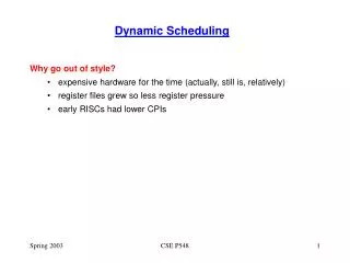
HW Schemes: Instruction Parallelism • Compiler or Static instruction scheduling can avoid some pipeline hazards. • e.g. filling branch delay slot. • Why in HW at run time? • Works when can’t know dependence at compile time • WAW can only be detected at run time • Compiler simpler • Code for one machine runs well on another • Key idea: Allow instructions behind stall to proceed DIVD F0,F2,F4 ADDD F10,F0,F8 SUBD F8,F8,F14 • Enables out-of-order execution => out-of-order completion • But, both structural and data hazards are checked in MIPS • ADDD is stalled at ID, SUBD can not even proceed to ID.
… RO EX1 … EXm WB (WAR?) IF ISSUE RO EX1 … EXn WB? (WAR?) … … RO EX1 … EXp WB? HW Schemes: Instruction Parallelism • Out-of-order execution divides ID stage: 1. Issue—decode instructions, check for structural hazards, Issue in order if the functional unit is free and no WAW. • Read operands (RO)—wait until no data hazards, then read operands • ADDD would stall at RO, and SUBD could proceed with no stalls. • Scoreboards allow instruction to execute whenever 1 & 2 hold, not waiting for prior instructions. Focusing on FP operations – assume no MEM stages
Scoreboard Implications • Out-of-order completion => WAR, WAW hazards • Solutions for WAR • CDC 6600: Stall Write to allow Reads to take place; Read registers only during Read Operands stage. • Tomasulo: Register Renaming • For WAW, must detect hazard: stall in the Issue stage until other completes • Need to have multiple instructions in execution phase => multiple execution units or pipelined execution units • Scoreboard replaces ID with 2 stages (Issue and RO) • Scoreboard keeps track of dependencies, state or operations • Monitors every change in the hardware. • Determines when to read ops, when can execute, when can wb. • Hazard detection and resolution is centralized.
Four Stages of Scoreboard Control 1. Issue—decode instructions & check for structural hazards (ID1) If a functional unit for the instruction is free and no other active instruction has the same destination register (WAW), the scoreboard issues the instruction to the functional unit and updates its internal data structure. If a structural or WAW hazard exists, then the instruction issue stalls, and no further instructions will issue until these hazards are cleared. 2. Read operands—wait until no data hazards, then read operands (ID2) A source operand is available if no earlier issued active instruction is going to write it, or if the register containing the operand is being written by a currently active functional unit. When the source operands are available, the scoreboard tells the functional unit to proceed to read the operands from the registers and begin execution. The scoreboard resolves RAW hazards dynamically in this step, and instructions may be sent into execution out of order.
Four Stages of Scoreboard Control 3.Execution—operate on operands (EX) The functional unit begins execution upon receiving operands. When the result is ready, it notifies the scoreboard that it has completed execution. 4.Write result—finish execution (WB) Once the scoreboard is aware that the functional unit has completed execution, the scoreboard checks for WAR hazards. If none, it writes results. If WAR, then it stalls the instruction. Example: DIVD F0,F2,F4 ADDD F10,F0,F8 SUBD F8,F8,F14 CDC 6600 scoreboard would stall SUBD until ADDD reads operands
Three Parts of the Scoreboard 1. Instruction status—which of 4 steps the instruction is in 2. Functional unit status—Indicates the state of the functional unit (FU). 9 fields for each functional unit Busy—Indicates whether the unit is busy or not Op—Operation to perform in the unit (e.g., + or –) Fi—Destination register Fj, Fk—Source-register numbers Qj, Qk—Functional units producing source registers Fj, Fk Rj, Rk—Flags indicating when Fj, Fk are ready and not yet read. Set to No after operand are read. 3. Register result status—Indicates which functional unit will write each register, if one exists. Blank when no pending instructions will write that register
Instruction status Issue Read operands Execution complete Write result Detailed Scoreboard Pipeline Control Wait until Bookkeeping Not busy (FU) and not result(D) Busy(FU)¬ yes; Op(FU)¬ op; Fi(FU)¬ `D’; Fj(FU)¬ `S1’; Fk(FU)¬ `S2’; Qj¬ Result(‘S1’); Qk¬ Result(`S2’); Rj¬ not Qj; Rk¬ not Qk; Result(‘D’)¬ FU; WAW Rj and Rk Rj¬ No; Rk¬ No Functional unit done "f((Fj( f )!=Fi(FU) or Rj( f )=No) & (Fk( f )!=Fi(FU) or Rk( f )=No)) "f(if Qj(f)=FU then Rj(f)¬ Yes);"f(if Qk(f)=FU then Rj(f)¬ Yes); Result(Fi(FU))¬ 0; Busy(FU)¬ No A.55 on page A-76 WAR
Scoreboard Example • The following numbers are to illustrate behavior, not representative • LD – 1 cycle • (compute address + data cache access) • ADDDs and SUBs are 2 cycles • Multiply is 10 cycles • Divide is 40 cycles
Scoreboard Example Cycle 2 Note: Can’t issue I2 because Integer unit is busy. Can’t issue next instruction due to in-order issue
Scoreboard Example Cycle 5 Now I2 is issued
Scoreboard Example Cycle 7 I3 stalled at read because I2 isn’t complete
Scoreboard Example Cycle 9 Note: I3 and I4 read operands because F2 is now available. ADDD (I6) can’t be issued because SUBD (I4) uses the adder
Scoreboard Example Cycle 11 Note: Add takes 2 cycles, so nothing happens in cycle 10. MUL continues.
Scoreboard Example Cycle 13 Now ADDD is issued because SUBD has completed
Scoreboard Example Cycle 15 Note: ADDD takes 2 cycles, so no change
Scoreboard Example Cycle 16 ADDD completes, but MULTD and DIVD go on
Scoreboard Example Cycle 17 ADDD stalls, can’t write back due to WAR with DIVD. MULT and DIV continue
Scoreboard Example Cycle 18 MULT and DIV continue
Scoreboard Example Cycle 19 19 MULT completes after 10 cycles
Scoreboard Example Cycle 20 MULTD completes and writes to F0
Scoreboard Example Cycle 21 Now DIVD reads because F0 is available
Scoreboard Example Cycle 22 ADDD writes result because WAR is removed.
Scoreboard Example Cycle 61 DIVD completes execution
Scoreboard Example Cycle 62 Execution is finished