Download
1 / 29
290 likes | 473 Views
Introduction of trigger system: E906 as an example. Shiuan-Hal,Shiu 05/02/2011 . Contents. Introduction Why we need trigger? An example of a trigger system in our daily life Trigger structure Hardware trigger Software trigger Trend of trigger system The E906 Trigger System.

E N D
Introduction of trigger system:E906 as an example Shiuan-Hal,Shiu 05/02/2011
Contents • Introduction • Why we need trigger? • An example of a trigger system in our daily life • Trigger structure • Hardware trigger • Software trigger • Trend of trigger system • The E906 Trigger System
Introduction • In the modern high energy experiments, a particle accelerator produces a large number of events for physicists to study. • Most of the events are not of interest. • A trigger system is to separate the interesting data(signal), and uninteresting data(background). • Trigger system can provide the timing information for the detector to look back the data at the corresponding moment.
Why trigger? • A high energy physics experiment can generate hundreds of petabyte of data in several months. • But the primary data of interest may be of the size of only several megabyte. • To analyze all the data may take too much CPU power. • The storage I/O dead time is much longer than all other detector components. • We can not handle all raw data without selection!!!
A well-known trigger system Trigger Trigger system Detector and DAQ system Holder system
Trigger structure • The general trigger structure consists of several steps. • First step: LV-1 trigger (Hardware trigger) • Most coarse and using a small subset of the whole data set of all the events. • Second step: LV-2 trigger (a mix of hardware and software trigger) • Finer than LV-1 and using a little larger data subset . • Final step: LV-3 trigger (Software trigger) • Finest and using the complete data set of the events which pass through the lower level stages.
Hardware triggering • Hardware triggering is the first level of event selection. • The hardware trigger must process all the events produced in the detector, it means the hardware trigger should be fast enough to keep up with the event rate and discriminating enough so that small amount of events are allowed to pass. • Some rapid response detectors are usually used for hardware trigger Ex: Scintillator detector. • Easy coincidence logic to determine the particle is used in hardware triggering.
Software triggering • Before events move on to software trigger, sometimes there is a hardware-software trigger, in which information from the slower detector is combined with computer processing. • After events have been selected with a hardware trigger or hardware-software trigger then software trigger take place to select the events. • Software trigger was designed to use commercial computer processors to compute additional event parameters or does partial event reconstruction to decide whether to keep it. • Software trigger is slowest but most comprehensive triggering layer.
Trigger system trend • LV-1 trigger: • Common usage of programmable units(FPGA) • We can implement look-up-table that was available only in the computer before. • Compactness. • The gap of LV-1 and LV-2 is disappearing. • LV-2 trigger: • Merged with LV-1. • LV-3 trigger: • Working at higher and higher rates. • Data transferring speed become faster and faster.
Trigger rate in some experiment * Input crossing rate
Main Injector 120 GeV Tevatron 800 GeV E906 trigger system-motivation • E906 is a fixed target experiment, using Fermilab Main injector to deliver 120GeV proton to collide 1H, 2H, and nuclear targets. • The antiquark in target proton and quark in incident proton will generate a muon pair via Drell-Yan process Fixed Target Beam lines
Motivation • The proton beam structure is 5 sec spill of 1*1013 protons each minute, it means when the proton comes we will have 2*1012protons in each seconds. • Right table shows the simulation results of event rate per second from the E906 fast MC. • There are two major backgrounds of E906, One is the di-muon decay from J/ψ the other is the random single muon coincidence which was decay from hadron. In order to separate the Drell-Yan dimuon from this two background, we need to define a trigger specifically for Drell-Yan process.
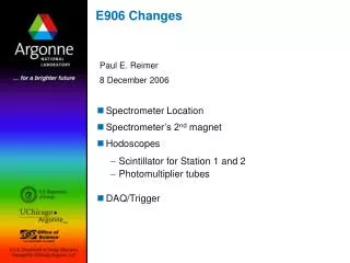
4.9m E906 Spectrometer Station 2 and 3: Hodoscope array Drift Chamber tracking Station 1: Hodoscope array MWPC tracking Solid Iron Focusing Magnet, Hadron absorber and beam dump Solid iron magnet • Sufficient Field with reasonable coils • Beam dumped within magnet Mom. Meas. (KTeV Magnet) Station 4: Hodoscope array Prop tube tracking 25m Liquid H2, d2, and solid targets • Experimental Challenge: • Higher probability of muonic decay for the produced hadrons. • Higher singles rates. • Larger multiple scattering for the muon traveling through hadron absorber and solid magnet.
NM4/KTeV Hall HODO 1 HODO 2 HODO 3 HODO 4
Data flow The proton beam structure is 5 sec spill of 1*1013 protons each minute 53MHz Four stations fast response hodoscope • Hardware trigger • CommercialFPGA board CAEN V1495 • Decision synchronous with RF clock LV1 All the data from each detectors are caught by this TDC/latch card which was designed by IPAS Chamber TDC /Latch by IPAS ~1KHz
Trigger electronic overview trigger supervisor level shifter y h o d o s c o p e x h o d o s c o p e (“times 4”) 2nd. v1495 TRIGGER μ 1st. v1495 1st. v1495 1st. v1495 1st. v1495 Online trigger system is composed of 5 CAEN V1495 FPGA modules. discriminator
V1495 • V1495 is a VME 6U board. • The I/O channel digital interface is composed by seven sections. • Section A and B are data input port, section C is a LVDS output port. D,E,F sections are user expandable port, in our experiment we define it to two input and one output port. DATA INPUT 64 PORT DATA INPUT 64 PORT RFINPUT DATAOUTPUT32PORT DATAOUTPUT 32PORT
Trigger hardware Here !
The main trigger • The trigger system searches for hit patterns through 4 station paddles. • All possible hit patterns are implemented into FPGAlook-up-table if( (A( 1)='1' AND B( 1)='1' AND D( 1)='1' ) OR (A( 1)='1' AND B( 1)='1' AND D( 2)='1' ) . . . OR (B(32)='1' AND D(32)='1' AND E(32)='1' ) ) then C(3)<='1'; elseif C(3)<='0'; end if; B B St.2 St.3 St.4 St.1
FPGA BLOCK diagram 53MHz RF clock RF input 53MHz 40MHz Local clock PLL 62.5MHz Retiming 250MHz/4 Phases Data input Sampling unit 1 Retiming (digitize) Memory Subtractor Look Up Table (pipeline mode) Sampling unit 2 Sampling unit 3 Lv1 512*9*8*3 Lv2 512*9*8*4 Sampling unit 4 Lv1 x96 Lv2 x128 One channel Delay control Retiming The block diagram here only shows the main function for trigger construction. Data output
How to program v1495 Two FPGA was built in v1495. FPGA “Bridge”, which is used for the VME interface and for the connection between the VME interface and the 2nd FPGA ( “USER PROGRAMMABLE FPGA”) User can use Quartus 2 to write the VHDL code to design the FPGA and generate a user firmware for the “USER PROGRAMMABLE FPGA”. We can upload the FPGA firmware via vme backplane bus without any toolkits.
Highlights of E906 trigger system • The trigger system have a dead time free, 1ns signal resolution. • We can adjust all channel’s delay from 0ns to 2048ns in 1ns step. • We use a subtractor, providing a 16ns jittering acceptable region. • The LV1 input signal rate is 53MHz and reduce to several KHz.
E906 Spectrometer: Bend Plane View Station 2 & 3 Drift Chambers 1700 Channels Multi-hit TDC’s M2 M2 Sta.1 M1 Target Sta.3 Sta.2 Sta.4 Muon ID wall MWPC 5500 Channels 256 Hodoscopes Station 4 Prop Tubes 400 Channels
What is pipeline step Data input Data output Stage1 LUT Stage2 LUT Stage3 LUT Stage4 LUT Stage5 LUT CLOCK if(F_temp_lv1_0( 0)='1' OR F_temp_lv1_0( 1)='1' OR F_temp_lv1_0( 2)='1' OR F_temp_lv1_0( 3)='1')then F_temp_lv2_0( 0)<='1'; else F_temp_lv2_0( 0)<='0'; end if; if(F_temp_lv1_0( 4)='1' OR F_temp_lv1_0( 5)='1' OR F_temp_lv1_0( 6)='1' OR F_temp_lv1_0( 7)='1')then F_temp_lv2_0( 1)<='1'; else F_temp_lv2_0( 1)<='0'; end if; if(A( 0)='1' AND B( 0)='1' AND D( 0)='1' )then F_temp_lv1_0( 0)<='1'; else F_temp_lv1_0( 0)<='0'; end if; if(A( 0)='1' AND B( 0)='1' AND D( 8)='1' )then F_temp_lv1_0( 1)<='1'; else F_temp_lv1_0( 1)<='0'; end if; Stage1 Stage2
pTx example • St2 No.7 • St3 No.8 • St4 N0.8 • Mean pTx = -3.329