Download
1 / 31
310 likes | 348 Views
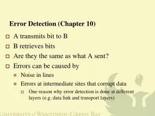
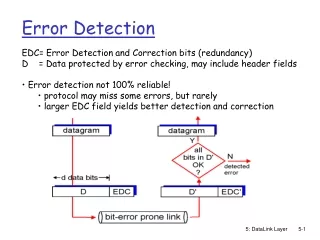
Error Detection. Error Detection and Correction. Background Data can be corrupted during transmission For reliable communication, errors must be detected and corrected Error detection and correction can be implemented in Data link layer, or Transport layer. Types of Errors.

E N D
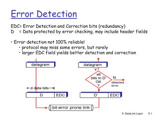
Error Detection and Correction • Background • Data can be corrupted during transmission • For reliable communication, errors must be detected and corrected • Error detection and correction can be implemented in • Data link layer, or • Transport layer
Single-Bit Error • Only one bit in the data units has changed • Example sent received 00000100 00001100
Burst Error • Two or more bits in the data unit have changed • Errors do not occur in consecutive bits • The length of the burst measured from the first corrupted bit to the last corrupted bit
Burst Error • Example length of burst error 7 bits sent 0000110000110000110 received 0011110010110000110
Detection : Redundancy • 1) Two copies of data unit (packet) are sent • Receiving device compares them • Able to detect errors • Transmission time double • Computational time slow
Detection : Redundancy • 2) Only extra information is added • Shorter group of bits may be added to each packet • Used by the receiving device • Discarded when it is used
Redundancy Check • Four types of redundancy checks • Vertical redundancy check (VRC) • Longitudinal redundancy check (LRC) • Cyclical redundancy check (CRC) • Checksum
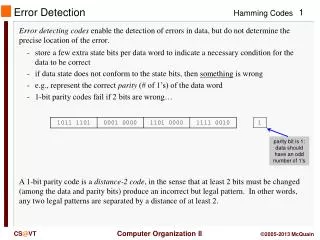
Vertical Redundancy Check(VRC) • Implemented in the physical layer • Most common and least expensive mechanism for error detection • Also called parity bit check • A redundant bit, called parity bit, is appended to every data unit • The number of 1s for each data unit, including the parity bit, becomes even • 0 is appended when the data unit consists of even 1s
VRC Original Data • 1110111 1101111 1100100 Parity Bit added • 11101110 11011110 11001001 Received data 11111110 11011110 11001001 Discard this data
VRC • Performance • Detects all single-bit errors (1, 3, 5, .. Bits changed) • Able to detect burst errors if • The total number of bits changed is odd • Cannot detect errors where the total number of bits changed is even
Longitudinal Redundancy Check(LRC) 1110011111011101 00111001 10101001 11100111 11011101 00111001 10101001 10101010 LRC 1110011111011101 00111001 10101001 10101010 Original data + LRC
Cyclic Redundancy Check (CRC) Based on Binary Division
CRCGenerator Data plus extra zeros. The number of zeros is one less than the number or bits in the divisor. When the leftmost bit is zero, we must use 0000 instead of the original divisor
CRC Checker • A CRC checker functions exactly like the generator • Data + CRC is divided by the predefined divisor • If the remainder is all 0s, accept • Otherwise discard the received data
Polynomial CRC generator (the divisor) is also represented as an algebraic polynomial It is short it can be used to prove the concept mathematically
Polynomial Polynomial properties : it should not be divisible by x it should be divisible by x+1 All burst errors of a length equal to the degree of polynomial are detected
Example of CRC Data = 1010001101 Polynomial = 110101 Calculate: 101000110100000 - 110101 = 011101110100000 Remainder = 1110 Send data frame = 10100011011110 Received Data = 10100011011110 Polynomial = 110101 Calculate: 101000110101110 - 110101 = 011101110101110 Remainder = 0
Checksum • Used by the higher-layer protocols • Based on concept of redundancy • Consists of checksum generator and checksum checker
Checksum • Checksum generator • The data unit is divided into k sections, each of n bits • All sections are added together using one’s complement to get the sum • The sum is complemented and becomes the checksum • The checksum is sent with the data
checksum • Checksum checker • The data unit is divided into k sections, each of n bits • All sections are added together using one’s complement to get the sum • The sum is complemented • If the result is zero, the data are accepted, otherwise, they are rejected
Example : Checksum Generator • (sender) 10101001 00111001 10101001 + 00111001 sum 11100010 checksum 00011101 Data sent 10101001 0011100100011101
Example : Checksum Checker • Received data 10101001 0011100100011101 • sum all sections 10101001 00111001 00011101 Sum 11111111 Complement 00000000 OK
Error Correction • Two methods • The sender retransmits the entire data • The receiver corrects errors using error-correction code • Error-correction code • More sophisticated than error-detection codes • Require more redundancy bits than error-detection
Error Correction (cont.) • Error-correction code (cont.) • The number of bits required to correct multiple-bit or burst error is high • In most case it is inefficient to do • Most error correction is limited to one-, two-, or three-bit errors
Error Correction • Self study if you are interested in it.